2.1 Connect Welding Interface (Digital)
2-4
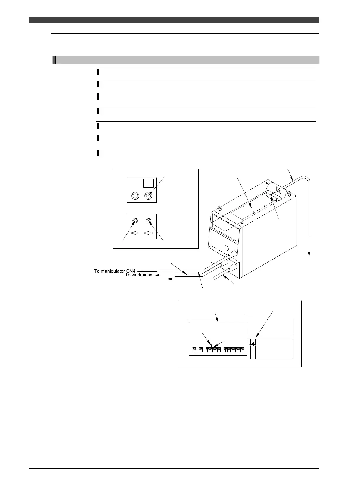
2.1.3 Connection of Control cable 5 (Welding power source side)
Cnnection of Welbee Inverter series wielding power source
1
Turn off the primary power supply and circuit breaker on the welding power source.
2
Remove the back cover on the welding power source.
3 Pull the connector of control cable 5 from the back of the welding power source and fix
the cable flange with the attached screws.
4 Connect the connector of control cable 5 to the connector CN17 on the printed circuit
board PCB1.
5
Connect the grounding cable to the grounding terminal.
6 Remove the “STOP” jumper wire connected to the terminal block TM3 on the printed
circuit board PCB10 in the welding power source.
7
Attach the back cover.
Output terminal (-) Output terminal (+)
Front (Lower)
Remove "STOP" jumper
wire.
Connect grounding cable.
Rear
Printed circuit board
PCB10
TM3
Printed circuit board
PCB1
CN17
Control cable 4
Torch side welding cable
Workpiece side welding cable
To wire feeder
Control cable 5
To robot controller
Socket for wire feeder
Front (Upper)
Figure 2.1.7 Cnnection of Welbee Inverter series wielding power source
 Loading...