3.10 Welding conditions of WB-P350/P400
3-31
3.10 Welding conditions of WB-P350/P400
This section describes the welding conditions that can be set when WB-P350 is connected.
3.10.1 About the welding condition parameters
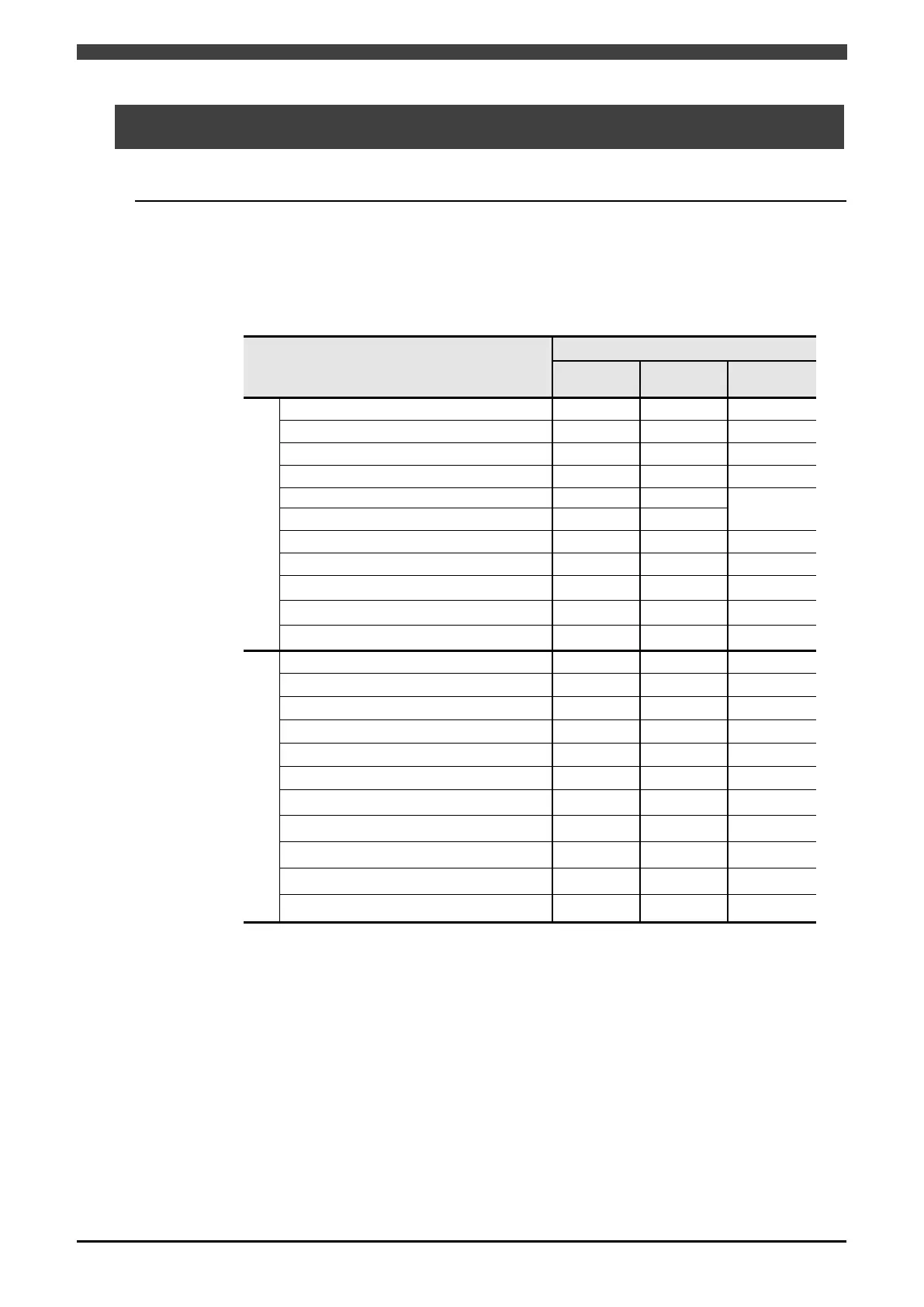
The welding conditions that can be set when WB-P350/P400 is connected using the interface
are shown in Table 3.10.1. Some welding conditions vary depending on the type of welding power
source registered in the robot controller. Welding condition parameters not included in this table
cannot be used.
Table 3.10.1 Welding conditions of WB-P350/P400
Condition
Welding method
DC DC pulsed
DC wave
AS
○
※
○
※
○
※
Current cond.
○ ○
○
Welding current / Wire speed
○ ○ ○
Welding voltage / Arc length tun. ○ ○ ○
○ ○ ○
Pulse arc characteristic ― ○ ○
Arc character. ○
―
―
Slope time / Slope distance
○ ○ ○
Initial current / Ini. wire speed ○ ○ ○
Initial voltage / Ini. arc length ○ ○ ○
Wave frequency
― ―
○
AE
○
※
○
※
○
※
○ ○ ○
Welding current / Wire speed
○ ○ ○
Welding voltage / Arc length tun.
○ ○ ○
○ ○ ○
○ ○ ○
Pulse arc characteristic
― ○
○
Arc character. ○
―
―
Slope time / Slope distance ○ ○
○
Wave frequency
― ―
○
Burnback adj. T.
― ○
○
○: Can be used
―: Cannot be used.
※: The welding mode displayed on the robot controller may be different from the welding mode
of the Welbee Inverter welding power source. For details, see "3.4.2 Configuring the welding
mode for the Welbee Inverter series welding power source".
 Loading...