3.13 Welding conditions of WB-A350P/A500P
3-57
Table 3.13.2 Arc end conditions of WB- A350 P/ A400P
Welding condition
Welding condition
AE
― 〇 〇
○ ○ ○
Crater time
○ ○
○
○ ○ ○
Retract speed
○ ○
○
○ ○ ○
Postflow robot ope
○ ○
○
Creaning width
― ○
○
― ○ ○
AC-DC switching frequency ― ― ○
― ― ○
Slope time / Slope distance
○ ○ ○
○ ○ ○
Wire precedence time
○ ○ ○
○: Can be used
―: Cannot be used.
3.13.2 Frequency during pulsed welding
Set the following conditions when pulsed welding (DC pulsed or AC pulsed) has been selected for
the welding mode.
- Pulse frequency (0.1 to 500 Hz)
- Pulse width ratio (5 to 95%)
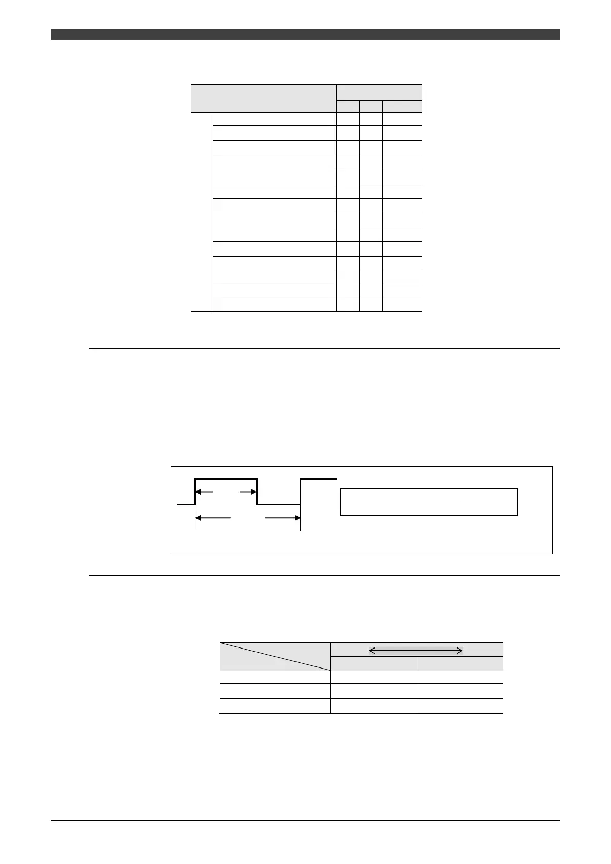
The pulse width ratio is the ratio of the peak current duration to one period expressed as a
percentage, and it is defined by the following expression.
Fig. 3.13.1 Pulse width ratio
3.13.3 Cleaning width
The cleaning width can be set for AC welding. A value in the range –20 to +20 can be set.
The following effects occur when the numerical value of the cleaning width is changed.
Table 3.13.3 Effect caused by an increase or decrease in cleaning width
Effect
Penetration depth Deeper Shallower
Electrode wear Less More
 Loading...