2.1 Connect Welding Interface (Digital)
2-1
2.1 Connect Welding Interface (Digital)
2.1.1 Installation of the Welding Interface (Digital) Board
Described here are the connections for the Welding Interface (Digital) Board that is used with the
robot controller.
1
Turn off the primary power supply and circuit breaker on the robot controller.
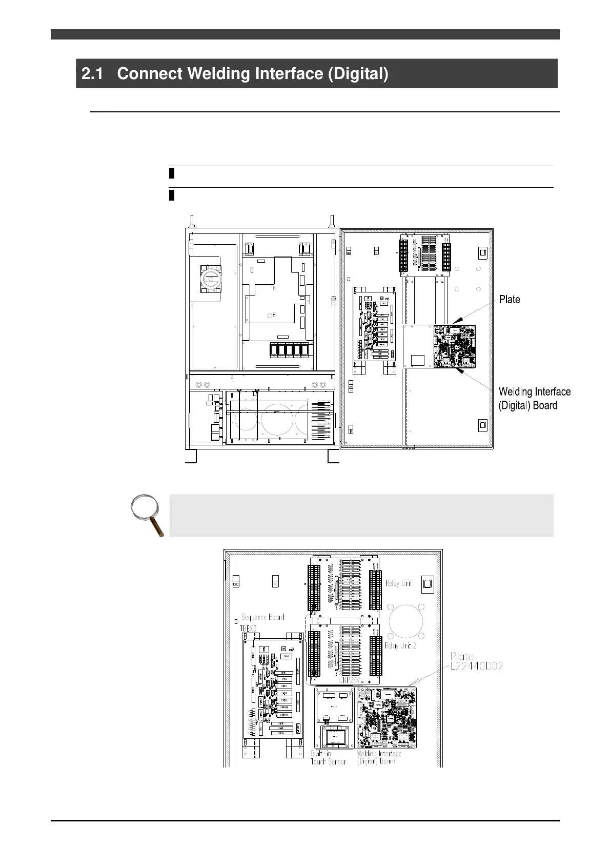
2 The Welding Interface (digital) board is fixed to the position shown in Figure 2.1.1 of the
robot controller by the plate and the locking card spacer.
Figure 2.1.1 Installation Positions of the Welding Interface (Digital) Board
INFO.
If you use two Relay Units and the Built-in Touch Sensor at the same time, the Built-in
Touch Sensor and the Welding Interface (Digital) Board are fixed to the position shown in
Figure 2.1.2.
Figure 2.1.2 Installation Positions of the Built-in Touch Sensor
 Loading...