2.1 Connect Welding Interface (Digital)
2-3
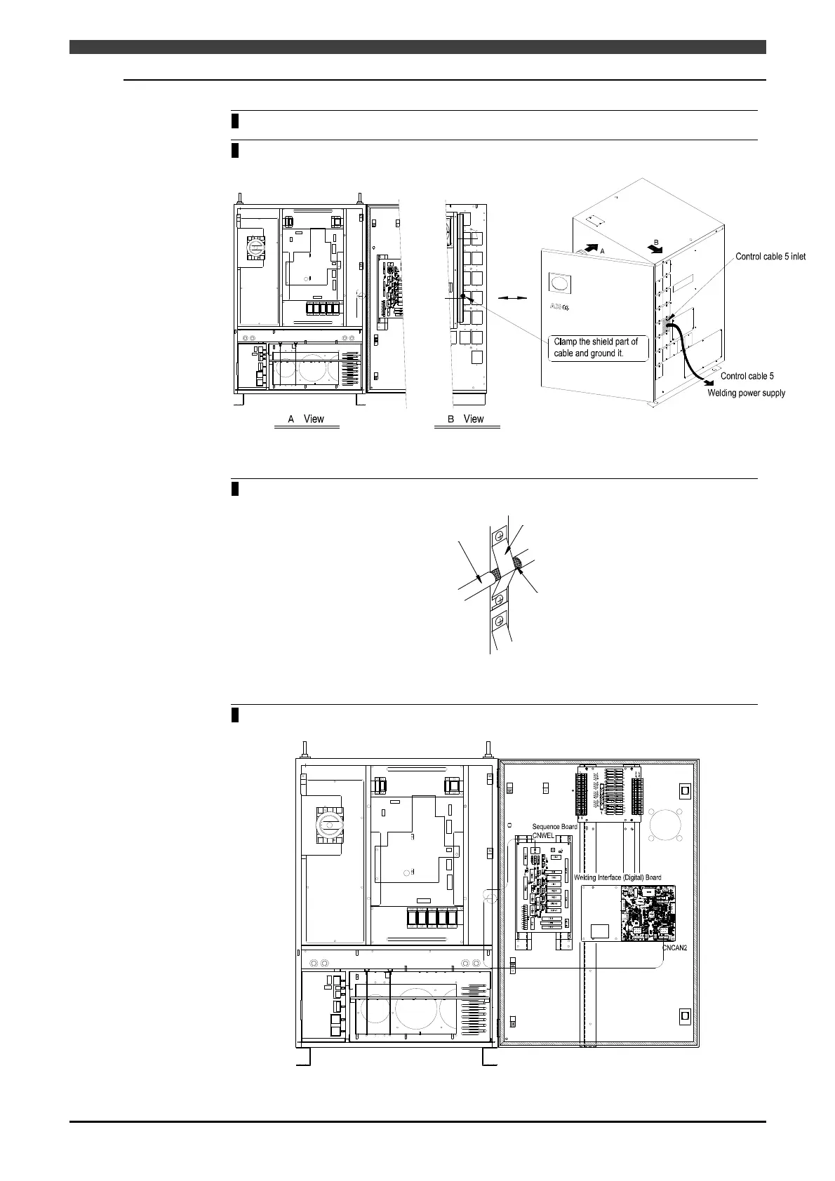
2.1.2 Connection of Control cable 5 (Robot controller side)
1
Turn off the primary power supply and circuit breaker on the controller.
2 Pull the control cable 5 connector through the control cable 5 inlet on the right side of the
robot controller as shown in Figure 2.1.4.
Figure 2.1.4 Connection of control cable 5 (Pull cable through)
3 Fix the shield section of the cables to the shield fixing fixtures on the left side of the
service entrance as shown in Figure 2.1.5.
Control cable 5
Shield ground
Shield fixing plate
Figure 2.1.5 Connection of control cable 5 (Fix the shielding ground)
4 Wire the cables as shown in Figure 2.1.6, and connect the Welding Interface (Digital)
Board CNCAN2 and the Sequence Board CNWEL.
Figure 2.1.6 Connection of control cable 5 (Cable wiring and connector connection)
 Loading...