3.9 Welding conditions of WB-M350/M400/M500
3-28
3.9 Welding conditions of WB-M350/M400/M500
This section describes the welding conditions that can be set when WB-M350/500 is connected.
3.9.1 About the welding condition parameters
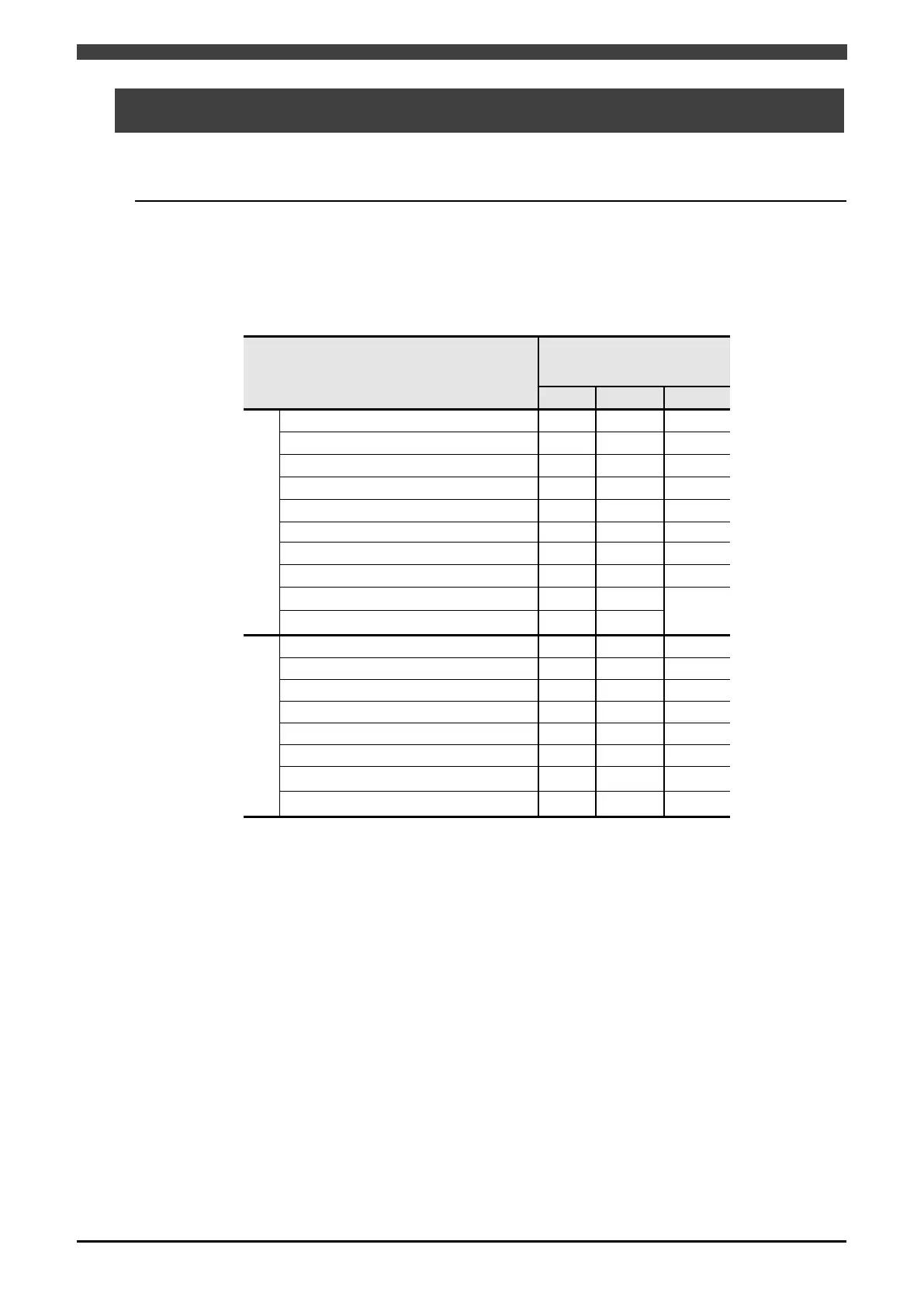
For the WB-M350/M400/M500 welding power source, the welding conditions shown in Table 3.9.1
can be set. Some welding conditions vary depending on the type of welding power source
registered in the robot controller. Welding conditions not included in this table cannot be used with
the interface.
Table 3.9.1 Welding conditions of WB-M350/M400/M500
Welding condition
registered
DM DM(S-2) DR
AS
Welding process
○
*
○
*
○
*
○ ○ ○
Penetration adjustment
× ×
×
Welding current / Wire speed
○ ○ ○
Welding voltage / Arc length tun. ○ ○ ○
○ ○ ○
○ ○ ○
Slope time / Slope distance
× ○
○
Initial current / Ini. wire speed
× ○ ○
Initial voltage / Ini. arc length × ○ ○
AE
○
*
○
*
○
*
○ ○ ○
Welding current / Wire speed
○ ○ ○
Welding voltage / Arc length tun.
○ ○ ○
○ ○ ○
○ ○ ○
Arc character. ○ ○ ○
Slope time / Slope distance × ○ ○
○: Can be used
×: Cannot be used (operates with the initial value of the welding power source)
*1: The welding mode displayed on the robot controller may be different from the welding mode of
the Welbee Inverter welding power source. For details, see "3.4.2 Configuring the welding
mode for the Welbee Inverter series welding power source".
 Loading...