4.19 SCR Cooling Manifold
TheSCRsarefastenedtotheSCRCoolingManifoldwhichremovesheatfromtheSCRsusingtherefrigerantthat
passesthroughitafterexitingtheInverterCoolingManifold.RefertoSection2.2MotorandPowerElectronics
Coolingonpage33.
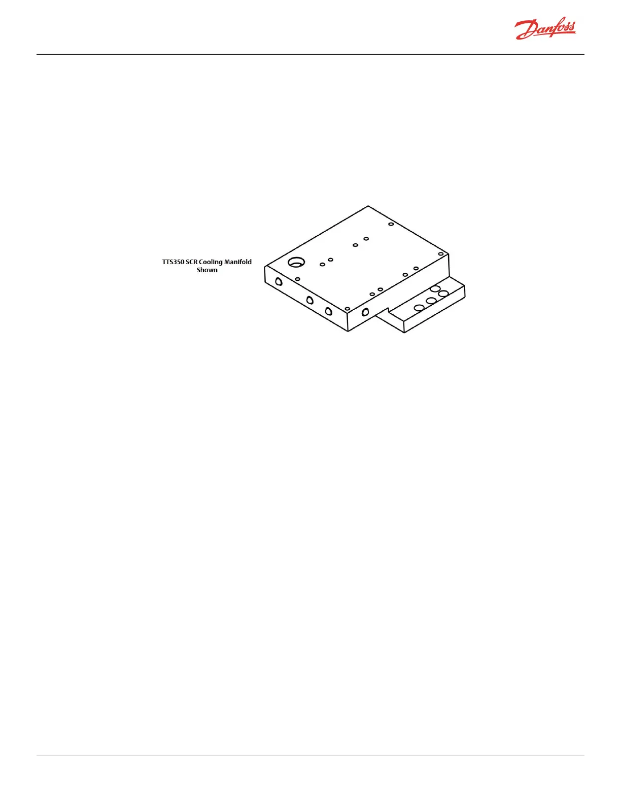
TherearedifferentstylesofSCRCoolingManifold.Theinstalledmanifoldwillvarydependingonthecompressor
model,appliedoptions,andrevision.WhilenotallSCRCoolingManifoldsareshownhere,theremovaland
installationstepsfromthevariousTTS/TTH/TGS/TGHcompressorsarethesame.
Figure 4-168 SCR Cooling Manifold
4.19.1 SCR Cooling Manifold General Removal Steps
1. IsolatethecompressorpowerasdescribedinSection1.8ElectricalIsolationonpage22.
2. Isolatethecompressorandrecovertherefrigerantaccordingtoindustrystandards.RefertoSection3.1
RefrigerantContainmentonpage41.
3. RemovethemainsinputcablesfromtheTerminalBlock.
4. RemovetheSoftStart.RefertoSection4.14.3SoftStartRemovalandInstallationonpage117.
5. ForTTS300/TGS230compressors,continuetoSection4.19.2SCRCoolingManifoldSpecificRemoval
Steps-TTS300/TGS230andforallotherTTS/TGS/TTH/TGHcompressors,continuetoSection4.19.3SCR
CoolingManifoldSpecificRemovalSteps-TTS/TGS/TTH/TGH(ExceptTTS300/TGS230)onpage159.
4.19.2 SCR Cooling Manifold Specific Removal Steps - TTS300/TGS230
1. RemovetheFuses.RefertoSection4.11.2.2Specific3-PhaseMainVoltageInputTerminalBlock
Removal-TTS300/TGS230onpage102.
2. RemovetheCapacitorCover.RefertoSection4.1.4.1CapacitorCoverRemovalandInstallationonpage
55.
3. IftheSCRCoolingManifoldistobereplaced,removetheSCRBusBars.RefertoSection4.15.1SCRDC
BusBarRemovalandInstallationonpage126.
4. RemovetheSCRs.RefertoSection4.18.3.2SCRRemoval-TTS300/TGS230onpage149.
5. RemovetheDCBusBarsandCapacitorAssembly.RefertoSection4.15.1SCRDCBusBarRemovaland
Installationonpage126.
6. RemovetheInverter.RefertoSection4.22.6InverterRemovalandInstallationonpage179.
M-SV-001-EN Rev. H-1/23/2023 Page 157 of 294