5. RemovetheLiquidLineconnectionfromthecompressorandinspectthestrainer.
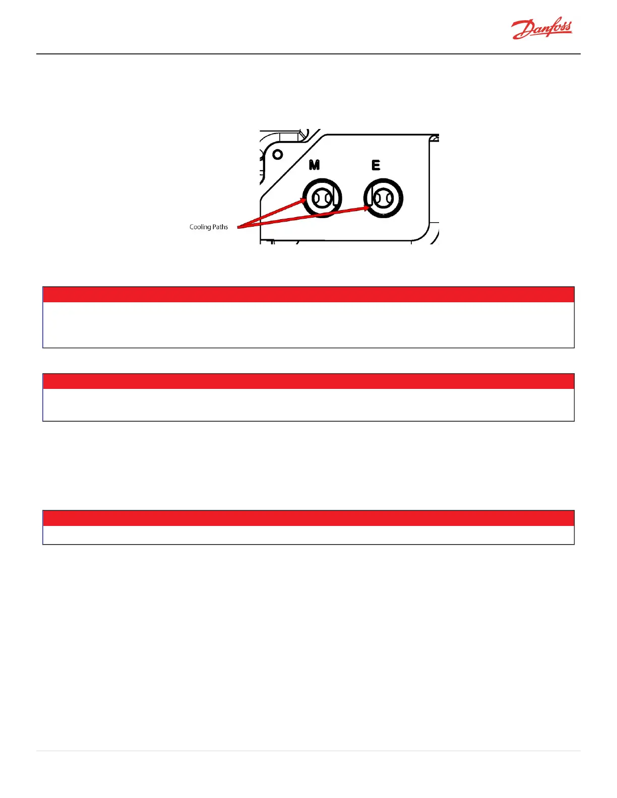
6. Ensurethatthecoolingpathsareclean,asshowninFigure4-34SolenoidCoolingPath-
TTS300/TGS230.
Figure 4-34 Solenoid Cooling Path - TTS300/TGS230
4.6.4 Solenoid and Coil Removal and Installation
NOTE
Oncertaincompressormodels,thesolenoidvalvebodiesmayhavedifferentorificesizesduetothesplit-coolingconfiguration.Itis
importanttonotgettheleftandrightconfusedwhenremovingandinstallingthesesolenoidbodies.RefertoFigure4-29Compressor
CoolingSolenoidCoilsonpage72.
• • • CAUTION • • •
Removalofthecompressorsolenoidswillreleaserefrigerant.Isolationandrecoveryoftherefrigerantmustbeperformedbyaqualified
servicetechnicianadheringtoindustry/ASHRAEstandards.
4.6.4.1 Solenoid and Coil Removal
1. Isolatecompressorpower.
2. Isolatethecompressorandrecovertherefrigerantaccordingtoindustrystandards.RefertoSection3.1
RefrigerantContainmentonpage41.
NOTE
Thereisnoneedtorecovertherefrigerantifonlythesolenoidcoilsarebeingremoved.
3. RemovetheServiceSideCover.RefertoSection4.1.3.1ServiceSideCoverRemovalandInstallationon
page54.
4. DisconnecttheSolenoidCoilJ16connectorfromtheBackplane.RefertoFigure4-31Backplane-J16
Connectoronpage73.
5. Removethesolenoidretainingnutsandthebeveledwashers.
6. Noteandmarkthepositionofeachcoil(leftandright)astheyneedtobeinstalledinthesame
orientationoncetherepairhasbeencompleted.
7. RemovetheSolenoidCoils.RefertoFigure4-35SolenoidComponentRemovalonpage76forthisand
thefollowingfour(4)steps.
8. Beforeremovingeithercoolingvalveassemblyfromthecompressorbody,identifywhichcoolingvalve
assemblygoestotheleftandtotherightpassageastheremaybedifferentorificesizes.Youcanuse
theengravingoneachorificebodytodeterminewhichgoesleftandright.Youshouldalsoverifythat
thenewcoolingvalveassembliesarethesameastheonesbeingremoved.
9. RemovetheSolenoid/TubePlungersusingasix-point13mmdeepsocket.
M-SV-001-EN Rev. H-1/23/2023 Page 75 of 294