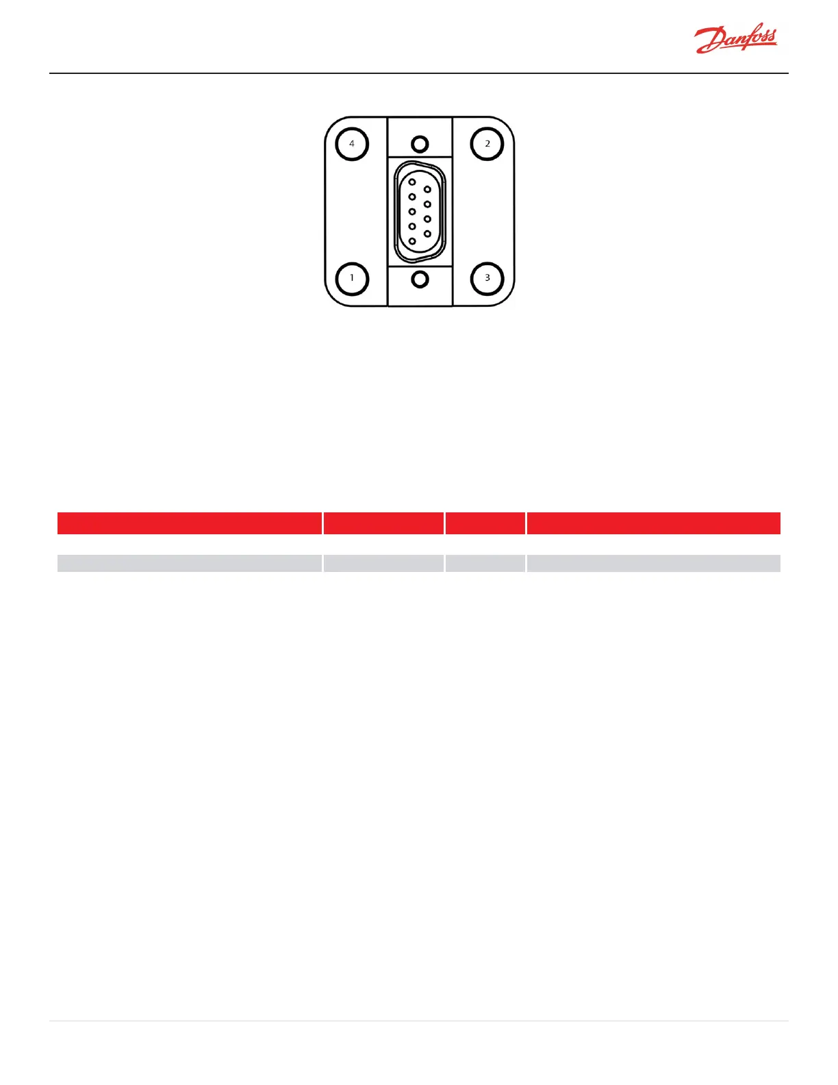
Figure 4-266 Bearing Sensor 9-Pin Feedthrough Connector Torque Sequence
7. Leaktestandevacuatecompressorinaccordancewithstandardindustrypractices.
8. Installthebearingsensorcableontothenew9-pinfeedthrough.(RefertotheBearingSensorCable
installsectionabove).
9. InstalltheServiceSideCover.RefertoSection4.1.3.1ServiceSideCoverRemovalandInstallationon
page54.
10. Returnthecompressortonormaloperation.
4.30.5.3 Bearing Sensor Torque Specifications
Table 4-49 Bearing Sensor Torque Specifications
Description Nm Ft.Lb. In.Lb.
BearingSensorFeedthroughfastener,M5x16 5 3.7 44
BearingSensorCableintegratedfasteners 0.5 0.4 4.4
Coverfastener,M5x15 1.5 - 13
M-SV-001-EN Rev. H-1/23/2023 Page 241 of 294