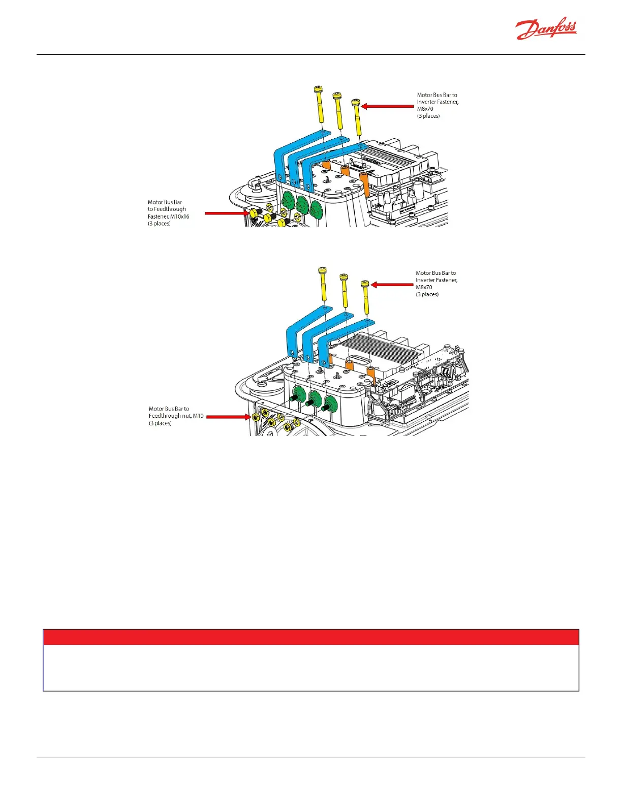
Figure 4-219 Motor Bus Bar Removal - PPS Feedthroughs
Figure 4-220 Motor Bus Bar Removal - Stainless-Steel Feedthroughs
4.23.5.2 Motor Bus Bar Installation
1. Placethemotorbusbarsintheircorrectlocations;theyaredesignedtoaligntoindividualbolt
patternsandshouldnotbeforced.
2. Looselyinstallthethree(3)M8x70fastenersthatsecurethemotorbusbarstotheinverteroutput
throughtheCopperTubes.ContinuetoStep3ifthecompressorcontainsPPSHigh-Power
Feedthroughs.ContinuetoStep4ifthecompressorcontainsStainless-SteelHigh-PowerFeedthroughs.
3. Installthethree(3)M10x16fastenersandlockwashersthatsecurethemotorbusbarstothePPSHigh-
PowerFeedthroughsandtorqueto14Nm(10ft.lb.).Becarefulnottoovertightentheboltstothe
powerfeedthroughs.ContinuetoStep5.
4. Installthethree(3)M10nutsandlockwashersthatsecurethemotorbusbarstotheStainless-Steel
High-PowerFeedthroughsandtorqueto15.5Nm(11.5ft.lb.).Becarefulnottoovertightentheboltsto
thepowerfeedthroughs.ContinuetoStep5.
• • • CAUTION • • •
WhiletorqueingtheHigh-PowerFeedthroughNuts,itisimportanttoholdtheinnernutwithawrench.Failuretodosocouldplacean
excessiveloadonthefeedthroughcausinginternaldamage.Also,thefeedthroughitselfcouldmovewhichcouldallowittoloosenorbe
overtorqued.
M-SV-001-EN Rev. H-1/23/2023 Page 197 of 294