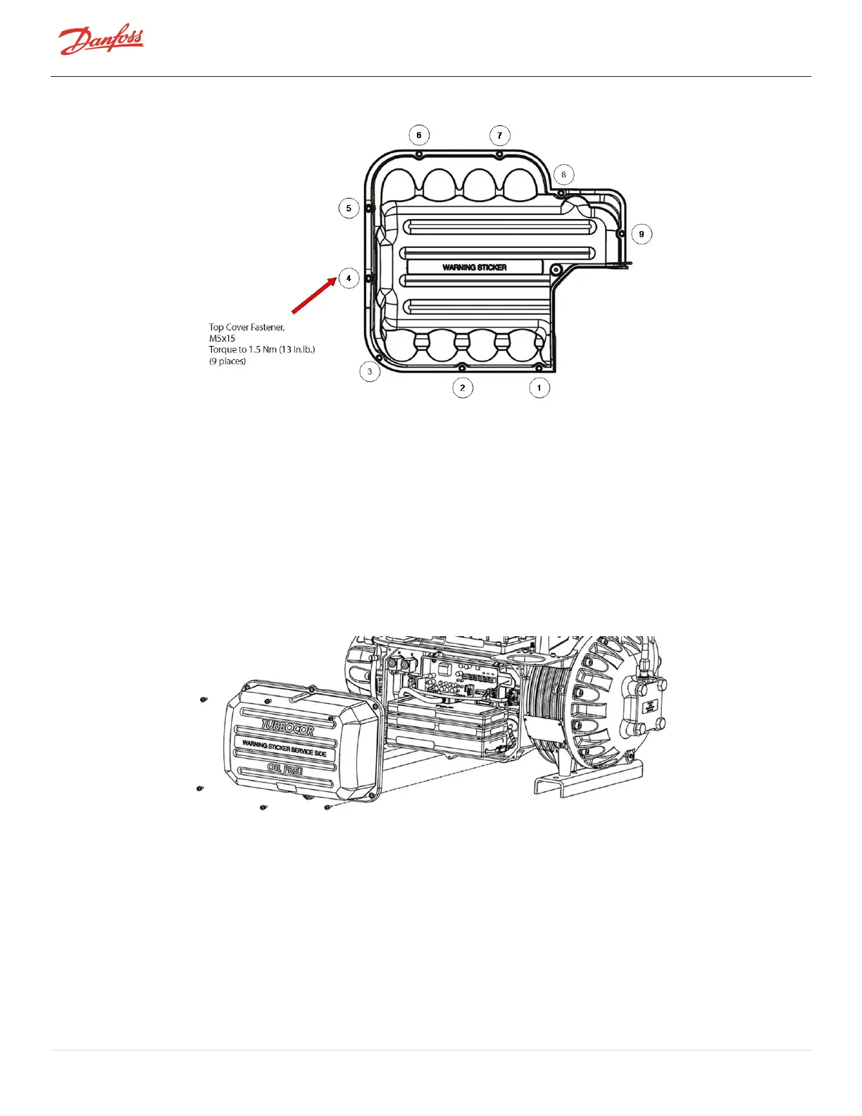
Figure 4-8 Top Cover Torque Sequence
3. EnsurethatnoresidueremainsonthecontactsurfacesoftheMainsInputCoverandcastingsides.
4. PlacetheMainsInputCoverandsecureitwiththeM5x15fasteners.Tightenaccordingtothesequence
showinFigure4-7MainsInputCoverTorqueSequenceonpage53.
5. Followthesequencetwice.Thefirsttime,onlytightenthefastenershalfwaydowntoallowfor
adjustment.Torqueto13in.lb.onthesecondpass.Tightenthe#4fasteneronlyonceandusecaution
astonotovertighten.
6. Returnthecompressortonormaloperation.
4.1.3 Service Side Cover
TheServiceSideCoverprovidesprotectionfortheBackplane,SerialDriver,BMCC,PWM,feedthroughs,andcabling.
Figure 4-9 Service Side Cover
4.1.3.1 Service Side Cover Removal and Installation
Service Side Cover Removal
1. RemovetheM5x15fastenersthatsecuretheServiceSideCover.
2. Removethecover.
Service Side Cover Installation
1. EnsurethatnoresidueremainsonthecontactsurfacesoftheServiceSideCoverandcompressor
housingsides.
Page 54 of 294 - M-SV-001-EN Rev. H 1/23/2023