Chapter 2.0 Compressor Fundamentals
Compressoroperationbeginswithademandsignalappliedtothecompressor.Thestartupsequenceis
configurableinthestartupsettings.SeetheOEMProgrammingManualforfurtherdetails.
2.1 Main Fluid Path
Thecompressorisatwo-stagecentrifugaltypecompressorutilizingvariablespeedastheprinciplemeansof
capacitycontrolwithinletguidevanes(IGVs)assistingwhenrequired.Refrigerantentersthefirststagesuctionside
ofthecompressorasalow-pressure,low-temperature,superheatedvapor.ItthenpassesthroughvariableIGVsthat
assistcompressorcontrolatpart-loadconditions.Bothimpellersaremountedonacommonshaft.Vaporpasses
throughthefirst-stageimpellerwherevelocityenergyisaddedtotherefrigerant.Thisisconvertedtoan
intermediatepressureinthefirst-stagevolute.Vaporthenentersthesecond-stageimpellerthroughadiffuser.In
thesecondstage,impellervelocityenergyisagainaddedtotherefrigerantandconvertedtothefinaldischarge
pressureinthedischargediffuserandvolute.Fromthesecond-stageimpeller,refrigerantpassesasahighpressure,
superheatedvaportothesystemdischargeline.
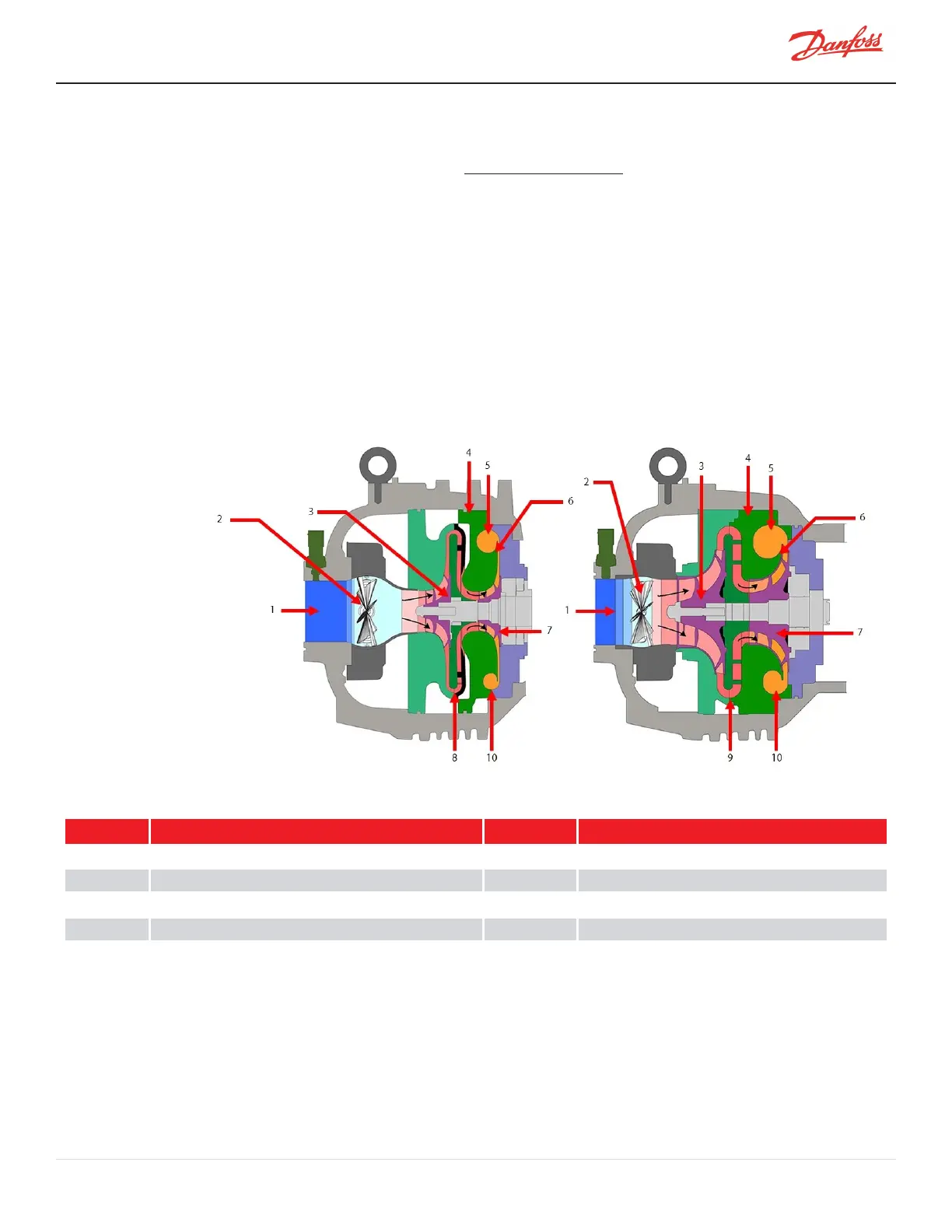
Figure 2-1 Compressor Fluid Paths
Table 2-1 Compressor Fluid Paths
No. Component No. Component
1
LowPressure/LowTemperatureGas
6 High-Pressure/HighTemperatureGas
2
InletGuideVanes(IGVs)
7 Second-StageImpeller
3
First-StageImpeller
8 VanedDiffuser
4
VoluteAssembly
9 VanelessDiffuser
5 DischargePort 10 De-SwirlVanes
2.2 Motor and Power Electronics Cooling
Liquidrefrigerant,havingatleast3.5°Kelvin/6.3°Rankinesub-coolingatconnectionpoint,mustbepipedtothe
compressorcoolinginletconnection.Thisconnectionisa1/2inchO-ringfaceseal(ORFS)connectionwithabuilt-in
strainer.RefertoFigure2-2CoolingInletAdapteronpage34foranexampleofthecoolinginletadapter.
M-SV-001-EN Rev. H-1/23/2023 Page 33 of 294