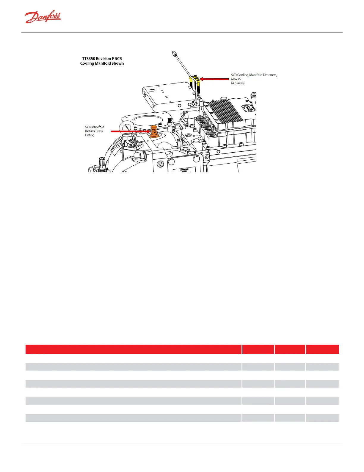
Figure 4-175 SCR Cooling Manifold Installation - TTS/TGS/TTH/TGH (Except TTS300/TGS230)
7. Leaktestandevacuatethecompressorinaccordancewithstandardindustrypractices.
8. ConnectthecompressorcableharnesstotheIGVMotorfeedthrough,suctionanddischargesensors,
andSCRTemperaturesensor(ifapplicable).
9. IftheSCRswereremovedpreviously,installtheSCRstotheSCRcoolingmanifold.TorquetheSCR
fastenersto5Nm(44in.lb.).
10. InstalltheDCBusBarandCapacitorassemblyovertheInverter.RefertoSection4.21.3DCCapacitor
BusBarAssemblyRemovalandInstallationonpage168.
11. InstalltheTerminalBlockAssembly.RefertoSection4.11.2.53-PhaseMainInputTerminalBlock
Installation-TTH/TGH/TTH/TGH(ExceptTTS300/TGS230)onpage105.
12. InstallthemainsinputcablestotheTerminalBlockandtorqueto21Nm(15ft.lb.).
4.19.6 SCR Cooling Manifold General Installation Steps
1. InstalltheSoftStart.RefertoSection4.14.3SoftStartRemovalandInstallationonpage117.
2. Installthetopcovers.RefertoSection4.1CompressorCoversonpage52.
3. Returnthecompressortonormaloperation.
4.19.7 SCR Cooling Manifold Torque Specifications
Table 4-32 Table 4-33 SCR Cooling Manifold Torque Specifications.
Description Nm Ft.Lb. In.Lb.
TTS300/TGS230ACBusBartoSCRfastener,M6x16 5 - 44
TTS300/TGS230DCBusBarstoSCRfastener,M6x16 5 - 44
DCCapacitorBusBartoSCRBusBarBolt,M6 10 7 89
SCRtoSCRCoolingManifoldfastener,M6x16 5 - 44
TTS300/TGS230SCRCoolingManifoldFastener,M6x20 7 - 62
TTS300/TGS230FusetoTerminalBlockfastener 4 - 35
SoftStartMountingFastener,M5x15orM5x20 5 - 44
GroundPostTopNut,5/16"-18UNC 7 - 62
GroundPostSecond(Jam)Nut,5/16"-18UNC 7 - 62
Page 162 of 294 - M-SV-001-EN Rev. H 1/23/2023