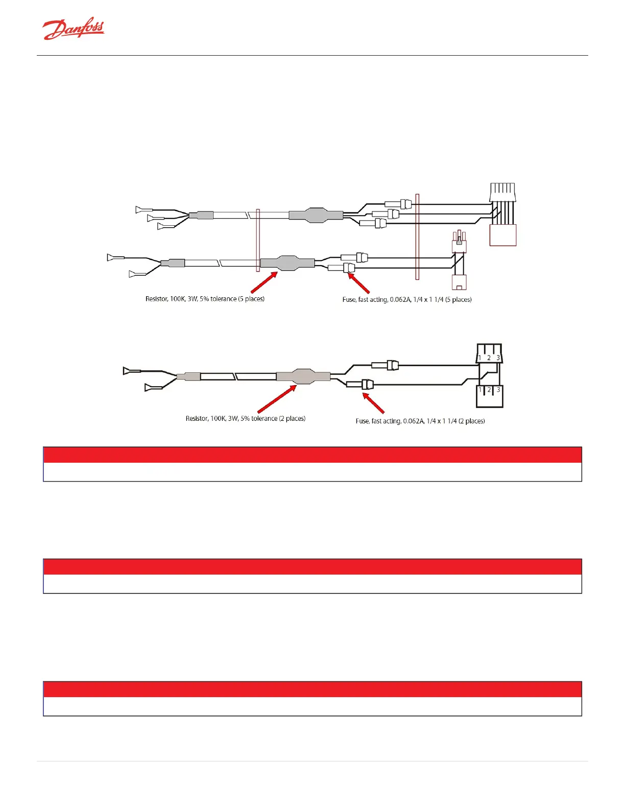
AllversionsoftheDCBusTestHarnesshavemale/femaleplugstoallowpiggybackconnectiontotherequired
voltagemeasurementpointsontheSoft-Start.RefertoFigure1-11DCBusTestHarnessDiagram(Closed-TopSoft
Start)andFigure1-12DCBusTestHarnessDiagram(Open-TopSoftStart)onpage26.foranexampleofthetwo
currentharnesses.Voltagemeasurementsaremadeviashroudedmultimeterjacksontheoppositeendofthe
cables.Cableandpersonalprotectionareprovidedbyinlinefast-actingfuses(1/4x11/4,62milliamp250V)and
current-limiting100kΩ3Wresistors.
Figure 1-11 DC Bus Test Harness Diagram (Closed-Top Soft Start)
Figure 1-12 DC Bus Test Harness Diagram (Open-Top Soft Start)
• • • CAUTION • • •
BeforeusingtheDCbustestharness,integrityofthefuses/resistorsintheharnessandcablemustbechecked.
1.10.1 General Verification and Installation of the DC Bus Test Harness
1. IsolatethecompressorpowerasdescribedinSection1.8ElectricalIsolationonpage22.
• • • CAUTION • • •
UseyourESDwriststrapbeforetouchingtheSoftStartBoardoranyelectroniccomponents.
2. UseanESDstrapandattachitthecompressorhousingwhileinstallingtheTestHarness.
3. RemovetheServiceSideCover.RefertoSection4.1.3.1ServiceSideCoverRemovalandInstallationon
page54.
• • • CAUTION • • •
UseyourESDwriststrapbeforetouchingtheSoftStartBoardoranyelectroniccomponents.
Page 26 of 294 - M-SV-001-EN Rev. H 1/23/2023