12. Removeanddiscardthetwo(2)O-rings.
13. RetaintheSCRManifoldforusewiththenewInverterassembly.
NOTE
Donotcompletelyremovethefoaminsulation,onlypullbackwhatisneededtoaccessthetwo(2)fasteners.
4.22.6.2 Compressor Specific Inverter Removal Steps - TTS/TGS/TTH/TGH (Except TTS300/TGS230)
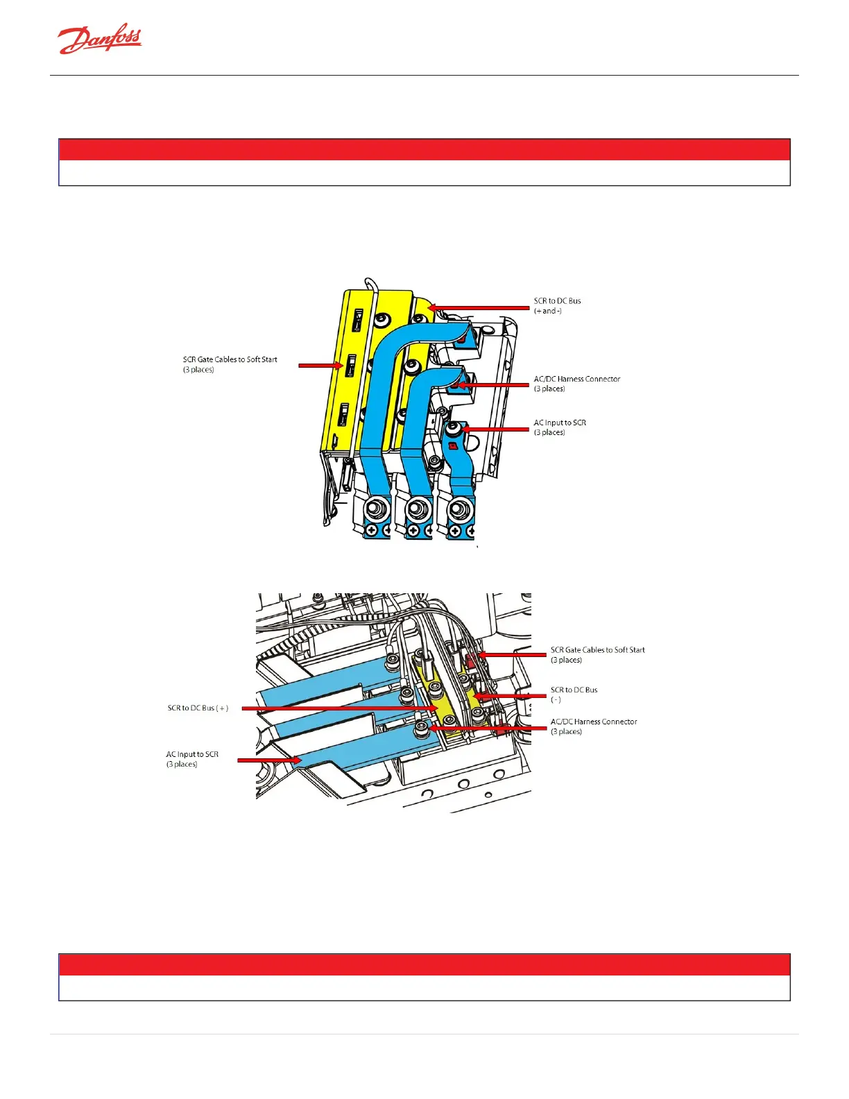
Figure 4-199 SCR Connections - TTS/TGS/TTH/TGH Rev. F and Earlier (Except TTS300/TGS230)
Figure 4-200 SCR Connections - TTS/TGS/TTH/TGH Rev. H (Except TTS300/TGS230)
14. RemovetheTerminalBlockandACMainsinputBusBars.RefertoSection4.11.23-PhaseMainVoltage
InputTerminalBlockRemovalandInstallationonpage102.
15. RemovetheSnubberCapacitorsandDCCapacitorBasBarAssembly.RefertoSection4.21.4.2DC
CapacitorBusBarAssemblyRemoval-TTS/TGS/TTH/TGH(ExceptTTS300/TGS230)onpage170.
16. Removethethree(3)M8x70MotorBusBarfastenersfromtheInverter.RefertoFigure4-201Inverter
CopperTubeRemoval-TTS/TGS/TTH/TGH(ExceptTTS300/TGS230)onpage183forthisandthe
followingstep.
NOTE
ItisnotnecessarytocompletelyremovetheMotorBusBars.
Page 182 of 294 - M-SV-001-EN Rev. H 1/23/2023