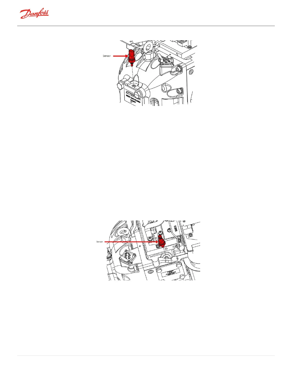
Figure 4-276 Suction Pressure/Temperature Sensor Removal
4.32.4.2 Suction Pressure/Temperature Sensor Installation
1. CheckandcleantheO-ring,housingthread,andO-ringsealingsurfaceintheIGVHousing.
2. ApplylubetoO-ring.
3. Insertthesensorandengagethefirstfewthreadsbyhand.
4. Usingadeep15/16"socket,tightenthesensorto10Nm(7ft.lb).
5. Reconnectthesensorconnector.
6. Leaktestandevacuateinaccordancewithstandardindustrypractices.
7. Returnthecompressortonormaloperation.
4.32.4.3 Discharge Pressure/Temperature Sensor Removal
1. IsolatethecompressorpowerasdescribedinSection1.8ElectricalIsolationonpage22.
2. Recovertherefrigerantaccordingtoindustrystandards.
3. Disconnectthesensorconnector.
4. Usingadeep15/16"socket,removethesensorfromthecompressorhousing.
Figure 4-277 Discharge Pressure/Temperature Sensor
4.32.4.4 Discharge Pressure/Temperature Sensor Installation
1. CheckandcleanO-ring,housingthread,andO-ringsealingsurfaceinthecompressorhousing.
2. ApplylubetoO-ring.
3. Insertthesensorandengagethefirstfewthreadsbyhand.
4. Usingadeep15/16"socket,tightenthesensorto10Nm(7ft.lb).
5. Reconnectthesensorconnector.
6. Leaktestandevacuateinaccordancewithstandardindustrypractices.
Page 248 of 294 - M-SV-001-EN Rev. H 1/23/2023