3.17.2 20-2* Feedback/Setpoint
This parameter group is used to determine how the PID
controller uses the 3 possible feedback signals to control
the output frequency of the frequency converter. This
group is also used to store the 3 internal setpoint
references.
Parameter 20-20 Feedback Function
This parameter determines how the 3 possible feedbacks
are used to control the output frequency of the frequency
converter.
NOTICE
Any unused feedback must be set to [0] No function in its
feedback source parameter 20-00 Feedback 1 Source,
parameter 20-03 Feedback 2 Source, or
parameter 20-06 Feedback 3 Source.
The feedback resulting from the function selected in
parameter 20-20 Feedback Function is used by the PID
controller to control the output frequency of the frequency
converter. This feedback can also be shown on the
frequency converter display, be used to control an analog
output, and be transmitted over various serial communi-
cation protocols.
The frequency converter can be congured to handle
multi-zone applications. 2 dierent multi-zone applications
are supported:
•
Multi-zone, single setpoint.
•
Multi-zone, multi-setpoint.
The dierence between the 2 is illustrated by the following
examples:
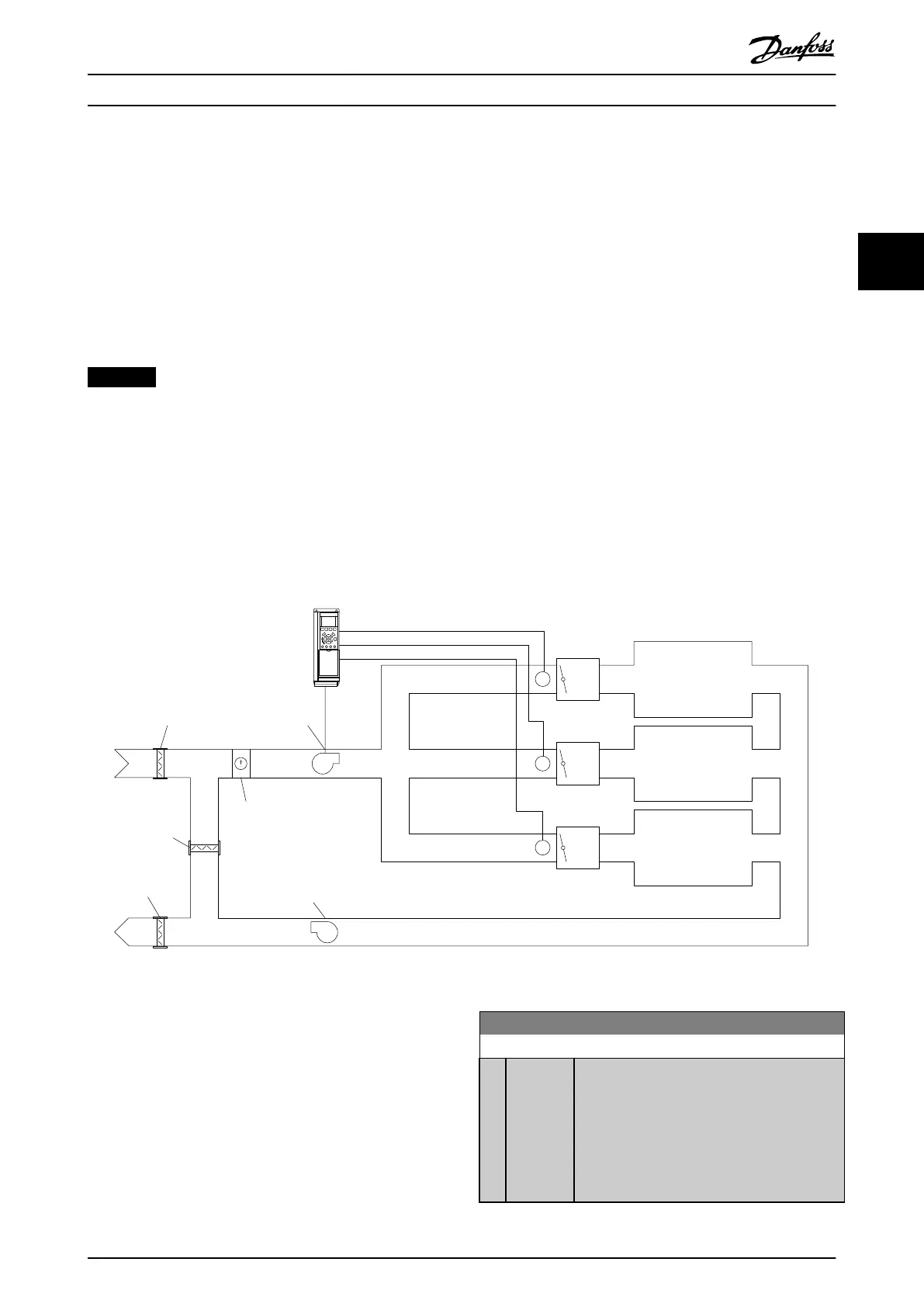
Example 1 – multi-zone, single setpoint
In an
oce building, a VAV (variable air volume) water
system must ensure a minimum pressure at selected VAV
boxes. Due to the varying pressure losses in each duct, the
pressure at each VAV box cannot be assumed to be the
same. The minimum pressure required is the same for all
VAV boxes. Select option [3] Minimum in
parameter 20-20 Feedback Function to set up this control
method. Enter the pressure in parameter 20-21 Setpoint 1.
The PID controller increases the speed of the fan if any
feedback is below the setpoint and decreases the speed of
the fan if all feedbacks are above the setpoint.
P
P
P
P
P
P
VAV
Box
Zone 1
Damper
Cooling/
heating coil
Supply
air fan
Return air fan
Damper
Damper
Zone 2
Zone 3
VAV
Box
VAV
Box
130BA353.10
Illustration 3.61 Multi-zone Application Scheme
Example 2 – multi-zone, multi-setpoint
The previous example illustrates the use of multi-zone,
multi-setpoint control. If the zones require dierent
pressures for each VAV box, each setpoint may be specied
in parameter 20-21 Setpoint 1, parameter 20-22 Setpoint 2,
and parameter 20-23 Setpoint 3. By selecting [5] Multi
setpoint minimum in parameter 20-20 Feedback Function,
the PID controller increases the fan speed if any feedback
value is below its setpoint. If all feedbacks are above their
individual setpoints, the PID controller decreases the fan
speed.
20-20 Feedback Function
Option: Function:
[0] Sum Sets up the PID controller to use the sum of
feedback 1, feedback 2, and feedback 3 as the
feedback.
The sum of setpoint 1 and any other references
that are enabled (see parameter group 3-1*
References) are used as the setpoint reference of
the PID controller.
Parameter Description Programming Guide
MG20OB02 Danfoss A/S © 05/2018 All rights reserved. 163
3 3

 Loading...


