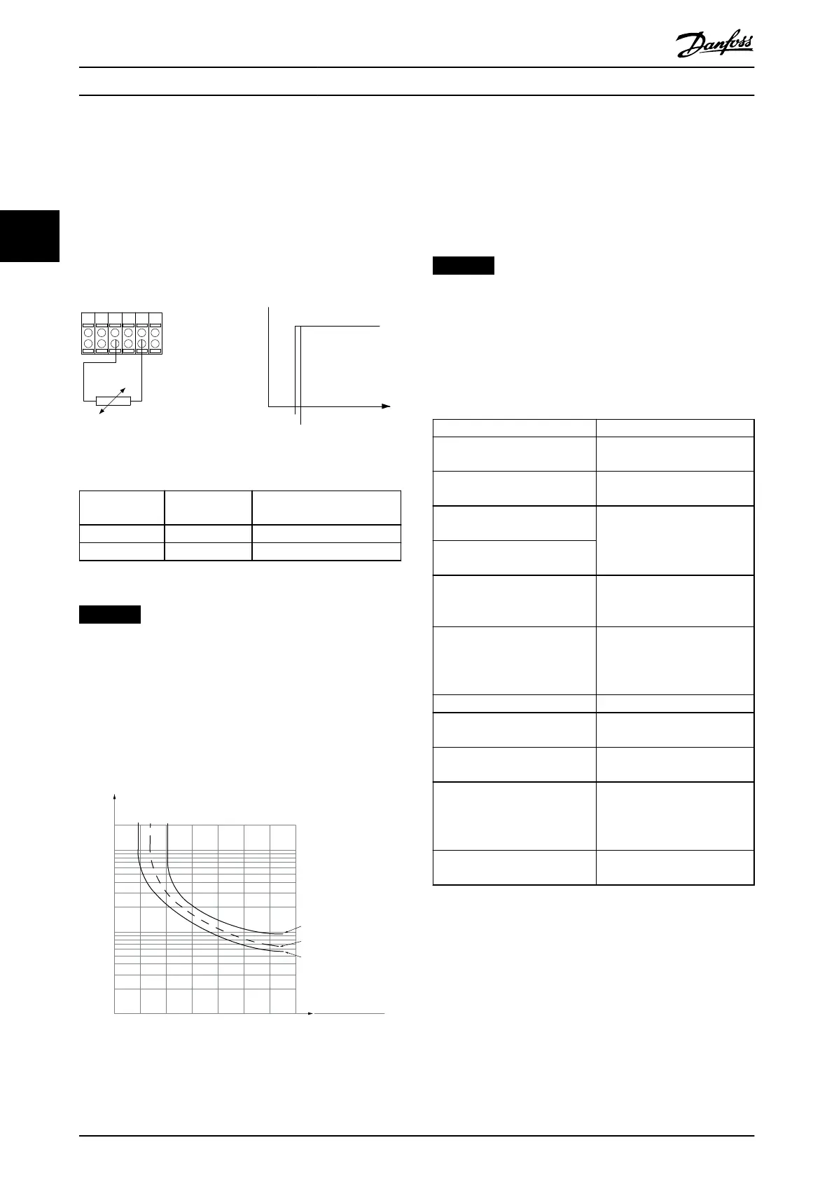
Using an analog input and 10 V as supply:
Example: The frequency converter trips when the motor
temperature is too high.
Parameter set-up:
•
Set parameter 1-90 Motor Thermal Protection to [2]
Thermistor Trip.
•
Set parameter 1-93 Thermistor Source to [2] Analog
Input 54.
555039 42 53 54
R
<3.0 k Ω
>3.0 k Ω
+10V
130BA153.11
PTC / Thermistor
OFF
ON
Illustration 3.14 PTC Thermistor Connection - Analog Input
Input
digital/analog
Supply voltage Threshold
cutout values
Digital 10 V
<800 Ω⇒2.7 kΩ
Analog 10 V
<3.0 kΩ⇒3.0 kΩ
Table 3.10 Threshold Cutout Values
NOTICE
Check that the selected supply voltage follows the
specication of the used thermistor element.
3.3.16 ETR
The calculations estimate the need for a lower load at
lower speed due to less cooling from the fan incorporated
in the motor.
1.21.0 1.4
30
10
20
100
60
40
50
1.81.6 2.0
2000
500
200
400
300
1000
600
t [s]
175ZA052.12
f
OUT
= 2 x f
M,N
f
OUT
= 0.2 x f
M,N
f
OUT
= 1 x f
M,N
(par. 1-23)
I
MN
(par. 1-24)
I
M
Illustration 3.15 ETR Prole
3.3.17 ATEX ETR
The VLT
®
PTC Thermistor Card MCB 112 oers ATEX-
approved monitoring of motor temperature. Alternatively,
an external ATEX-approved PTC protection device can be
used.
NOTICE
Only use ATEX Ex-e-approved motors for this function.
See the motor nameplate, approval certicate, datasheet,
or contact motor supplier.
When controlling an Ex-e motor with increased safety, it is
important to ensure certain limitations. The parameters
that must be programmed are presented in Table 3.11.
Function Setting
Parameter 1-90 Motor Thermal
Protection
[20] ATEX ETR
Parameter 1-94 ATEX ETR cur.lim.
speed reduction
20%
Parameter 1-98 ATEX ETR interpol.
points freq.
Motor nameplate.
Parameter 1-99 ATEX ETR interpol
points current
Parameter 1-23 Motor Frequency Enter the same value as for
parameter 4-19 Max Output
Frequency.
Parameter 4-19 Max Output
Frequency
Motor nameplate, possibly
reduced for long motor cables,
sine-wave lter, or reduced
supply voltage.
Parameter 4-18 Current Limit Forced to 150% by 1-90 [20]
Parameter 5-15 Terminal 33
Digital Input
[80] PTC Card 1
Parameter 5-19 Terminal 37 Safe
Stop
[4] PTC 1 Alarm
Parameter 14-01 Switching
Frequency
Check that the default value
fullls the requirement from
the motor nameplate. If not,
use a sine-wave lter.
Parameter 14-26 Trip Delay at
Inverter Fault
0
Table 3.11 Parameters
Parameter Description
VLT
®
AQUA Drive FC 202
60 Danfoss A/S © 05/2018 All rights reserved. MG20OB02
33

 Loading...


