MATRIX 300N™ REFERENCE MANUAL
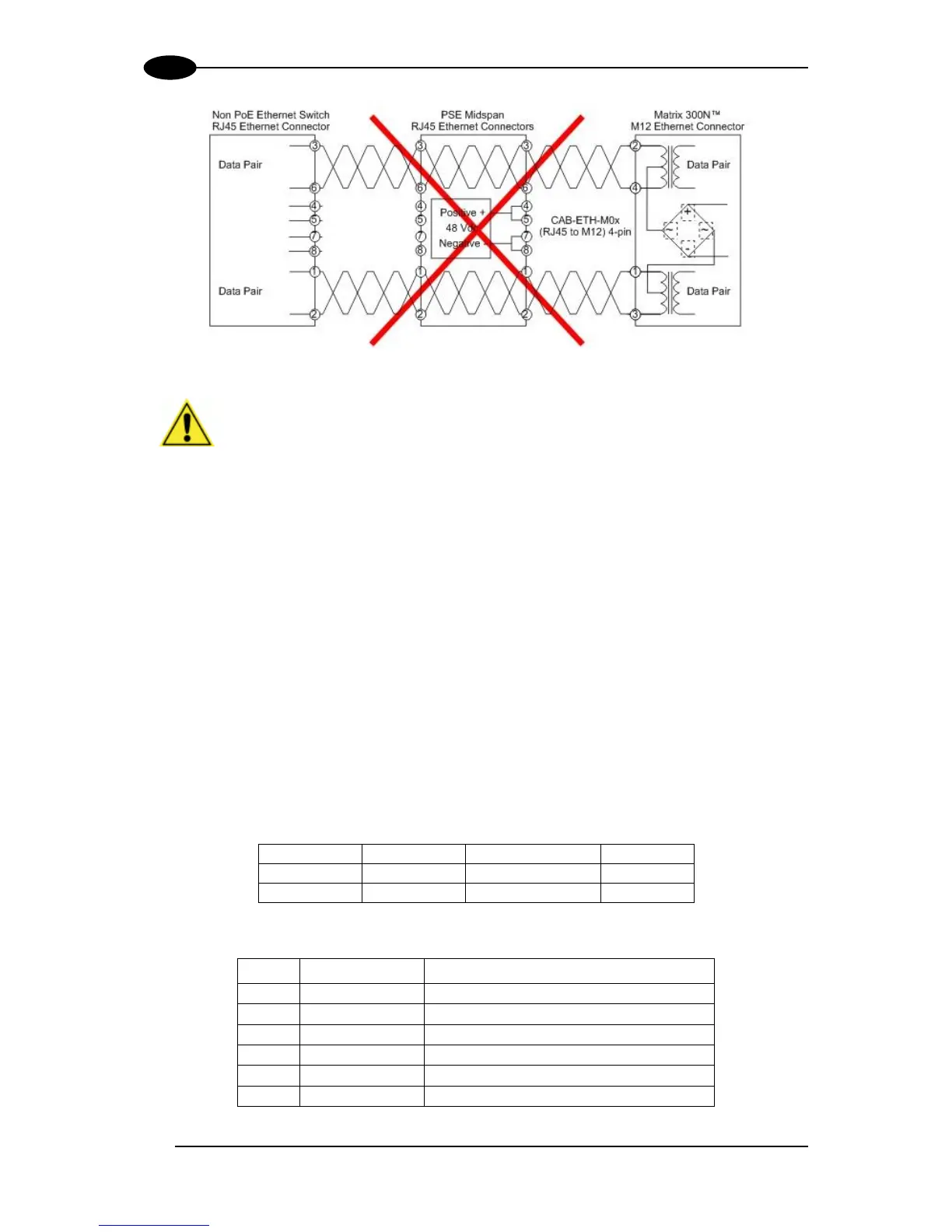
Figure 84 – Matrix 300N PoE PSE Midspan Alternative B Connections NOT SUPPORTED
CAUTION: For Matrix 300N PoE models, the internal Digital Output circuitry
is not powered and supply power is not available to any Input/Output devices
(Vdc=0). Only input device signals can be accepted directly on the M12
17-pin connector without power.
For these models, if it is necessary to use Input/Output devices, we recommend
connecting them through the CBX, which must be powered separately.
ID-NET NETWORK TERMINATION
The network must be properly terminated by a 120 Ohm resistor at the first and last reader of
the network.
INPUTS
There are two optocoupled polarity insensitive inputs available on the M12 17-pin connector
of the reader: Input 1 (External Trigger) and Input 2, a generic input. See par. 4.5 for more
details.
The electrical features of both inputs are:
The relative pins on the M12 17-pin connector are:
Power Supply input voltage +
External Trigger A (polarity insensitive)
External Trigger B (polarity insensitive)
Input 2 A (polarity insensitive)
Input 2 B (polarity insensitive)
Power Supply input voltage -

 Loading...


