5 TYPICAL LAYOUTS
The following typical layouts refer to system hardware configurations. However, they also
require the correct setup of the software configuration parameters. Dotted lines in the figures
refer to optional hardware configurations within the particular layout.
NOTE: All software configurations are made through DL.CODE which
connects to the reader through the on-board Ethernet interface.
5.1 ETHERNET CONNECTION
The Ethernet connection is possible in two different layouts.
In a Point-to-Point layout the reader is connected to a local host by using a CAB-ETH-M0x
cable. There is no need to use a crossover adapter since Matrix 300N incorporates an
autocross function.
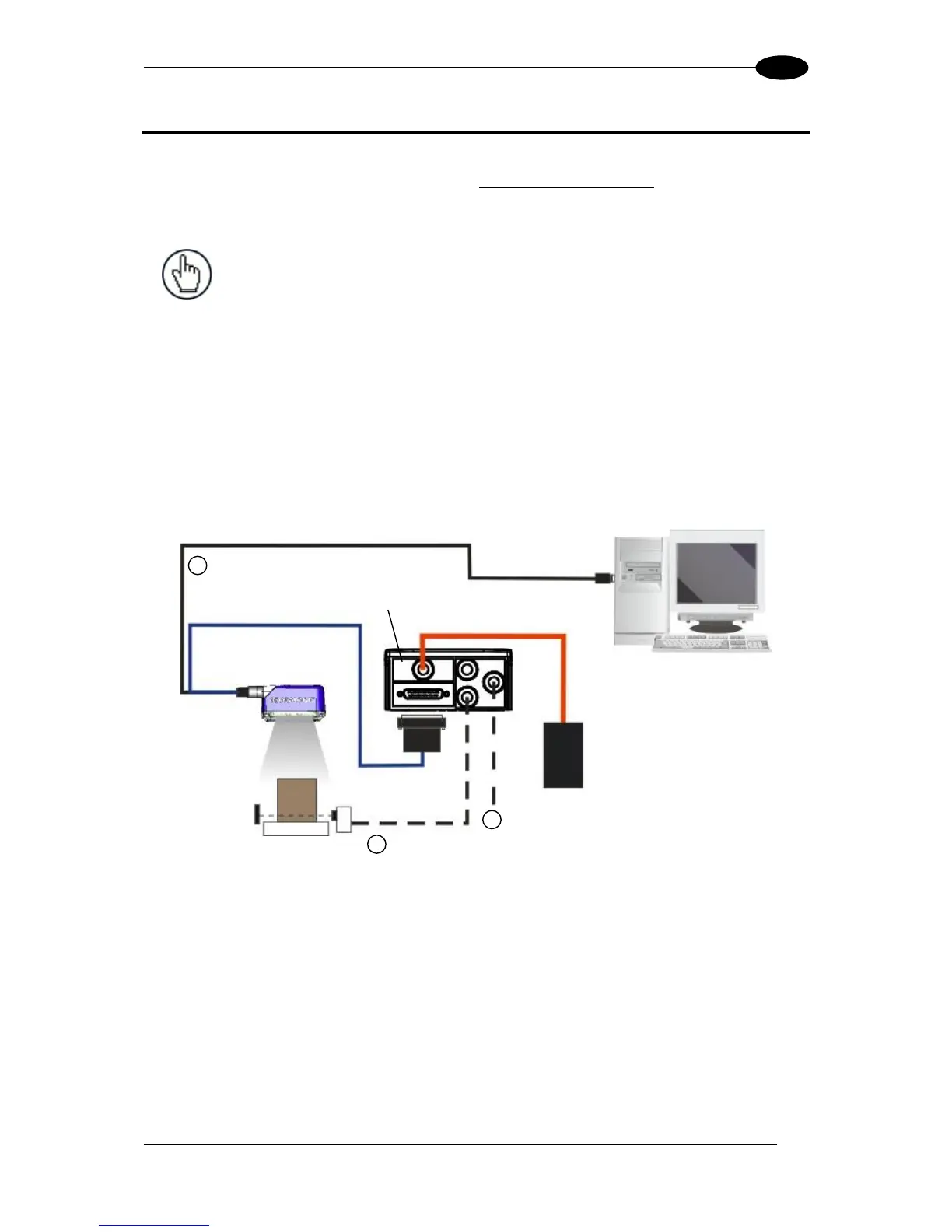
Figure 58 - Ethernet Point-to-Point Layout
Ethernet Interface
Auxiliary Serial Interface (RS232 – Data Monitor)
External Trigger (for One Shot or Phase Mode)

 Loading...


