Adjustments and Maintenance
2-12
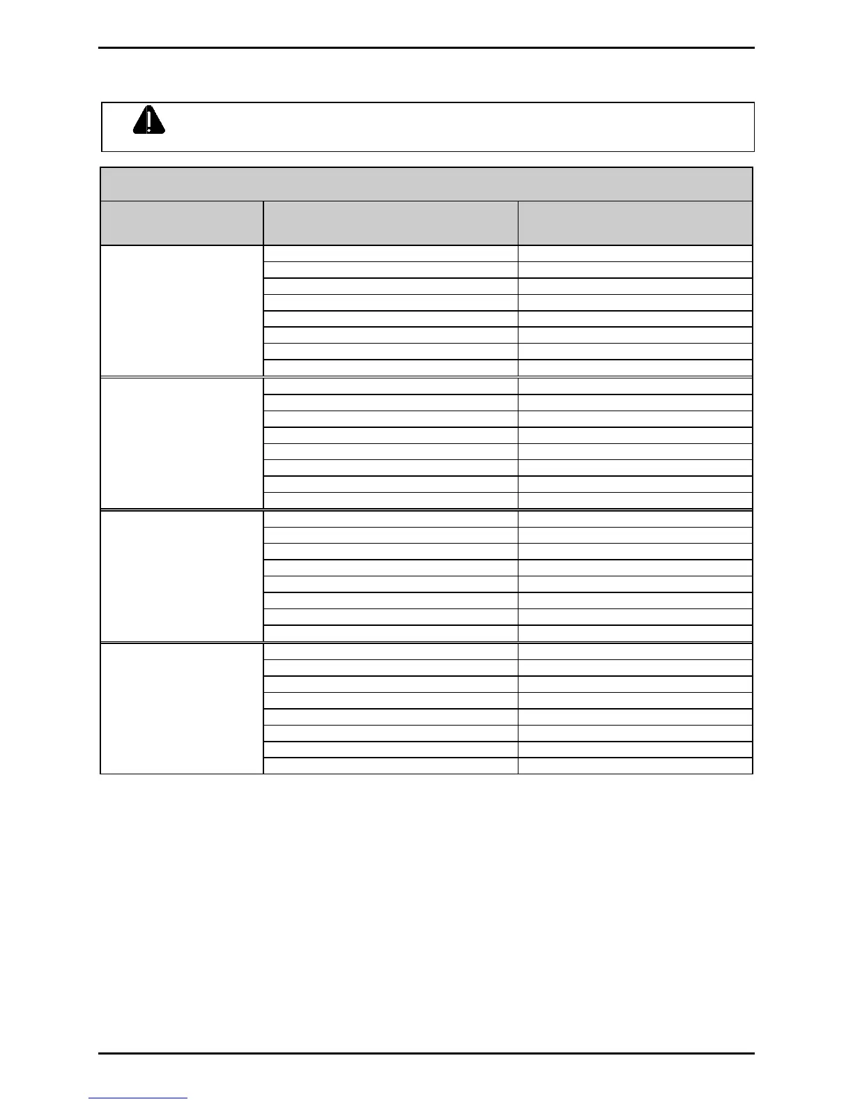
WARNING
NEVER exceed the recommended Printhead Voltage; permanent damage or
shortened service life can result.
Printhead Voltage Adjustment Table
Printer
Model
Printhead Resistance
(ohms)
Printhead Voltage
(+/- 0.1 Volt DC)
561 – 586 22.4
587 – 611 22.9
612 – 635 23.3
636 – 660 23.8
661 – 685 24.2
686 – 710 24.7
711 – 734 25.1
I4206,
I4208,
I4210,
&
I4212
735 – 759 25.5
947 – 989 22.4
990 – 1030 22.9
1031 – 1072 23.4
1073 – 1114 23.8
1115 – 1156 24.2
1157 – 1197 24.7
1198 – 1239 25.1
I4308
1240 – 1281 25.5
935 – 976 22.4
977 – 1018 22.9
1019 – 1059 23.3
1060 – 1100 23.8
1101 – 1141 24.2
1142 – 1183 24.7
1184 – 1224 25.1
I4406
1225 – 1265 25.5
1530 – 1598 22.4
1599 – 1665 22.9
1666 – 1733 23.4
1734 – 1800 23.8
1801 – 1868 24.2
1869 – 1935 24.7
1936 – 2003 25.1
I4604
2004 – 2070 25.5
2.3 Ribbon Path Alignment
If irregular voids extend intermittently, diagonally through an image printed with ribbon, the cause
may be due to ribbon overlap (wrinkling). However, other factors can be involved. Begin
troubleshooting by verifying correct adjustment of the Leveling Cam (Section 2.2.1), Printhead
Pressure (Section 2.2.2), and Burn Line (Section 2.2.3). Also, examine the platen for wear, debris
buildup, and excessive lateral movement. If all of these adjustments and components are in good
order, then perform a Ribbon Path Alignment as follows:
 Loading...


