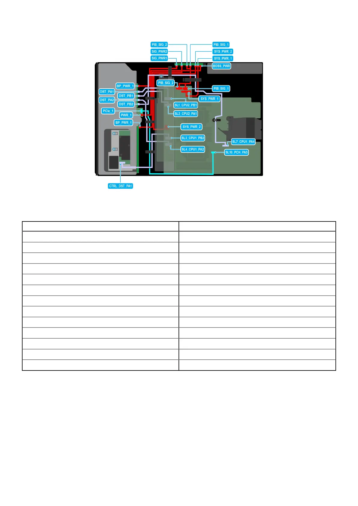
Figure 90. Cable routing - 8 x 3.5-inch + 8 x 2.5-inch NVMe with BOSS S2 module
Table 33. Cable routing - 8 x 3.5-inch + 8 x 2.5-inch NVMe with BOSS S2 module
From To
PCIe_1 (Signal connector on BOSS S2 module) SL10_PCH_PA5 (Signal connector on system board)
PWR_1 (Power connector on BOSS S2 module) BOSS_PWR (Power connector on PIB)
CTRL_DST_PA1 (Signal connector on PERC) SL3_CPU1_PB2 (Signal connector on system board)
BP_PWR_1 (Power connector on backplane) SIG_PWR_1 (Power connector on PIB)
DST_PA1 (Signal connector on backplane) SL1_CPU2_PB1 (Signal connector on system board)
DST_PB1 (Signal connector on backplane) SL2_CPU2_PA1 (Signal connector on system board)
DST_PA2 (Signal connector on backplane) SL4_CPU1_PB2 (Signal connector on system board)
DST_PB2 (Signal connector on backplane) SL7_CPU1_PA4 (Signal connector on system board)
BP_PWR_1 (Power connector on backplane) SIG_PWR_2 (Power connector on PIB)
SYS_PWR_1 (Power connector on system board) SYS_PWR_1 (Power connector on PIB)
SYS_PWR_2 (Power connector on system board) SYS_PWR_2 (Power connector on PIB)
PIB_SIG_1 (Power connector on system board) PIB_SIG_1 (Power connector on PIB)
PIB_SIG_2 (Power connector on system board) PIB_SIG_2 (Power connector on PIB)
Installing and removing system components 95