Table 48. Connector descriptions for SATA/NVMe
From To
BP_PWR_1 (backplane power connector) SIG_PWR_0 (system board power connector)
BP_DST_SA1 (backplane SATA connector) SL3_PCH_SA1 (signal connector on the system board)
BP_DST_PA1(backplane PCIe cable connector) SL1_CPU1_PB2 (signal connector on the system board)
BP_DST_PB1 (backplane PCIe cable connector) SL2_CPU1_PA2 (signal connector on the system board)
BP_DST_PA2 (backplane PCIe cable connector) SL4_CPU2_PB3 (signal connector on the system board)
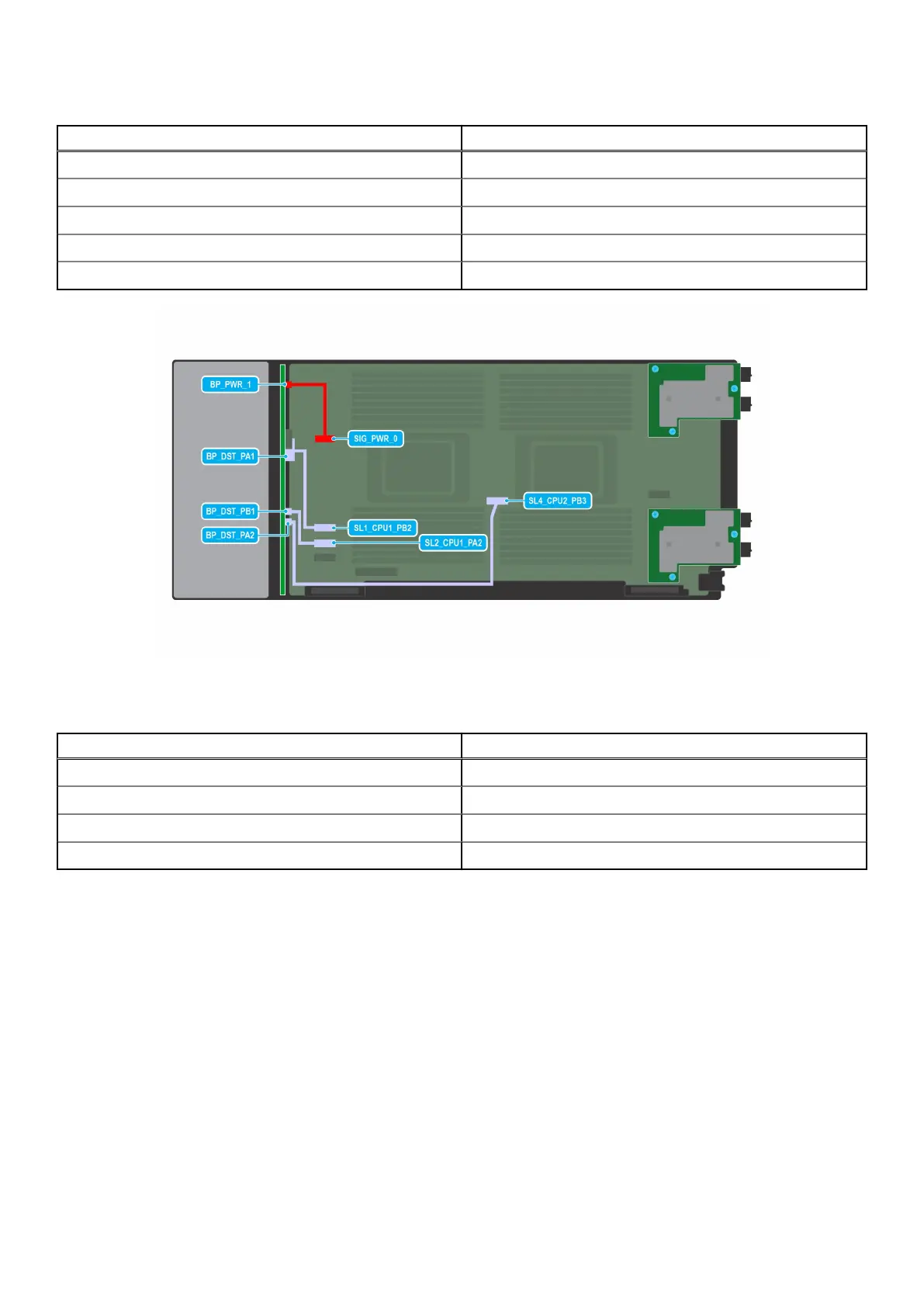
Figure 53. NVMe cabling diagram of configuration 1 - 6 x 2.5-inch universal backplane
Table 49. Connector descriptions for NVMe
From To
BP_PWR_1 (backplane power connector) SIG_PWR_0 (system board power connector)
BP_DST_PA1(backplane PCIe cable connector) SL1_CPU1_PB2 (signal connector on the system board)
BP_DST_PB1 (backplane PCIe cable connector) SL2_PCU1_PA2 (signal connector on the system board)
BP_DST_PA2 (backplane PCIe cable connector) SL4_CPU2_PB3 (signal connector on the system board)
84 Installing and removing system components