● Maximum supported speed of the DIMMs
NOTE: MT/s indicates DIMM speed in MegaTransfers per second.
The system supports Flexible Memory Configuration, enabling the system to be configured and run in any valid chipset
architectural configuration. The following are the recommended guidelines for installing memory modules:
● All DIMMs must be DDR5.
● Mixing of non-3DS and 3DS RDIMMs is not allowed.
○ 3DS is a DRAM technology used to manufacture the highest capacity DIMMs. Refer to your DIMM documentation for
additional details.
● x4 and x8 DRAM based memory modules cannot be mixed.
●
If memory modules with different speeds are installed, they operate at the speed of the slowest installed memory module(s).
● Populate memory module sockets only if a processor is installed.
○ For single-processor systems, sockets A1 to A16 are available.
○ For dual-processor systems, sockets A1 to A16 and sockets B1 to B16 are available.
○ A minimum of 1 DIMM must be populated for each installed processor.
● In Optimizer Mode, the DRAM controllers operate independently in the 64-bit mode and provide optimized memory
performance.
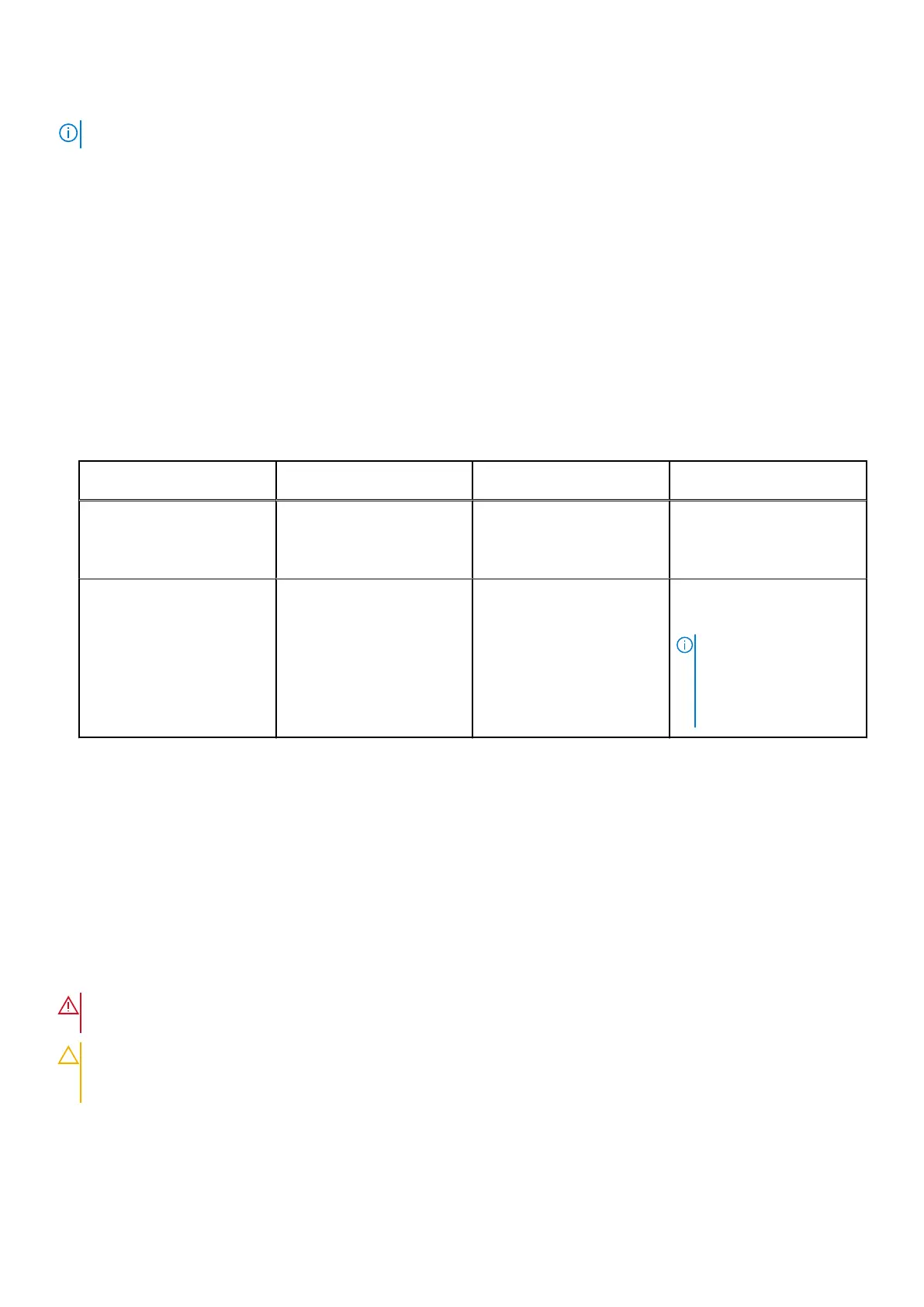
Table 63. Memory population rules
Processor Configuration Memory population Memory population
information
Single processor Optimizer (Independent
channel) population order
A{1}, A{2}, A{3}, A{4}, A{5},
A{6}, A{7}, A{8}, A{9},
A{10}, A{11}, A{12}, A{13},
A{14}, A{15}, A{16}
1, 2, 4, 6, 8, 12 or 16 DIMMs
are allowed.
Dual processor (Start with
processor1. Processor 1
and processor 2 population
should match)
Optimizer (Independent
channel) population order
A{1}, B{1}, A{2}, B{2}, A{3},
B{3}, A{4}, B{4}, A{5}, B{5},
A{6}, B{6}, A{7}, B{7} A{8},
B{8}, A{9}, B{9}, A{10},
B{10}, A{11}, B{11}, A{12},
B{12}, A{13}, B{13}, A{14},
B{14}, A{15}, B{15}, A{16},
B{16}
2, 4, 8, 12, 16, 24 and 32
DIMMs are supported per
system.
NOTE: Optimizer
population order is not
traditional for 8 and 16
DIMMs installations for
dual processor.
● Populate all the sockets with white release tabs first, followed by the sockets with black release tabs.
● Mixing of more than two memory module capacities in a system is not supported.
● Unbalanced or odd memory configurations result in a performance loss, and the system may not identify the memory
modules being installed. Always populate memory channels identically with equal DIMMs for best performance.
● Supported RDIMM configurations are 1, 2, 4, 6, 8, 12, or 16 DIMMs per processor.
Removing a memory module
Prerequisites
1. Follow the safety guidelines listed in the Safety instructions.
2. Follow the procedure listed in Before working inside your system. .
3. Remove the air shroud.
WARNING:
The memory modules are hot to touch for some time after the system has been powered off. Allow
the memory modules to cool before handling them.
CAUTION: To ensure proper system cooling, memory module blanks must be installed in any memory socket that
is not occupied. The memory module blanks compatible with the MX760c are DDR5 gray color blanks. Remove
memory module blanks only if you intend to install memory modules in those sockets.
Steps
1. Locate the appropriate memory module socket.
Installing and removing system components
95