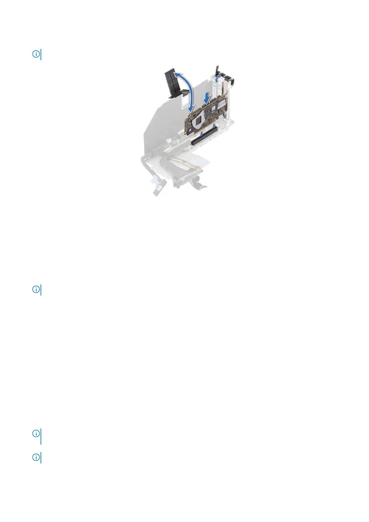
6. Tilt and push the card holder to hold the card in the riser.
NOTE: The numbers on the image do not depict the exact steps. The numbers are for representation of sequence.
Figure 108. Installing an expansion card into the expansion card riser
Next steps
1. If required, connect the cables from the risers to the system board.
2. Install the expansion card risers.
3. Install the riser air shroud after installing the riser 2 and VGA bracket.
4. If opened, close the cable holder on the system board.
5. If removed, install the PEM.
6. If removed, connect all the UPI cables and riser cables to the PEM connectors, observe the cable routing.
NOTE: See cable routing section for more information.
7. If removed, connect the BOSS-N1 signal and power cable to the connectors on the BOSS module.
8. Install the air shroud.
9. Install the cooling fan cage assembly.
10. Install the air shroud top cover.
11. Install the support bar.
12. Follow the procedure listed in After working inside your system.
13. Install any device drivers required for the card as described in the documentation for the card.
Removing the full length expansion card risers
Prerequisites
1. Follow the safety guidelines listed in the Safety instructions.
2. Follow the procedure listed in the Before working inside your system.
3. Remove the support bar.
4. Remove the air shroud top cover.
5. Remove the cooling fan cage assembly.
6.
NOTE:
If BOSS-N1 module is installed, be sure to disconnect the BOSS-N1 power cable and signal cable before
removing the riser 1 cage.
7. Disconnect all the riser cables from the PEM connectors, observe the cable routing.
NOTE: See cable routing section for more information.
8. For supported riser configurations, see the Expansion card installation guidelines section.
142
Installing and removing system components