Cable routings
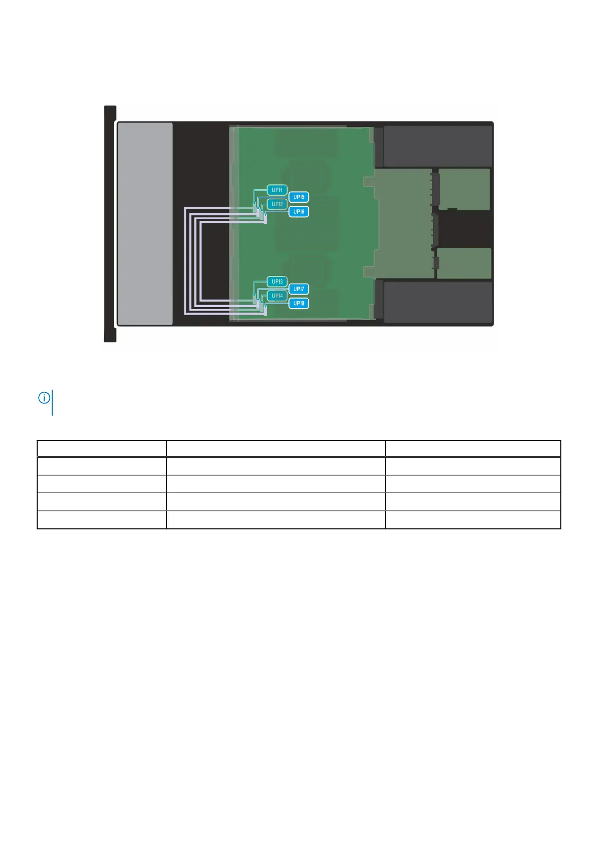
Figure 59. Configuration 0: UPI cables
NOTE:
Follow the sequential order as shown in the table to remove the cables, to install the cables follow the reverse
sequential order.
Table 66. UPI cables
Order From To
1 UPI1 (UPI signal connector on system board) UPI8 (UPI signal connector on PEM)
2 UPI2 (UPI signal connector on system board) UPI7 (UPI signal connector on PEM)
3 UPI3 (UPI signal connector on system board) UPI6 (UPI signal connector on PEM)
4 UPI4 (UPI signal connector on system board) UPI5 (UPI signal connector on PEM)
Installing and removing system components 97