VFD-L Series
DELTA ELECTRONICS, INC. ALL RIGHTS RESERVED
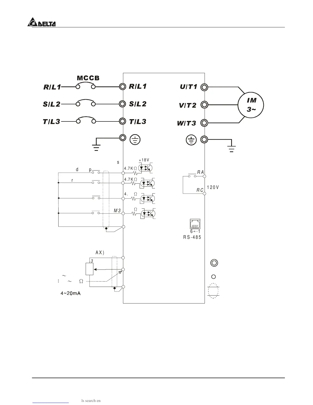
3.1 Basic Wiring Diagram
Users must connect wiring according to the circuit diagram shown below. Please follow all
National and State wiring codes, when wiring the VFD-L.
87
97
:7
,0
a
'
è
5/
6/
7/
è
è
è
è
Power supply for Potentiometer
Multi-function indication
Control circuit terminals
If the AC Drive model is VFD002L11A/B, VFD004L11A/B, VFD002L21B, VFD004L21B
or VFD007L21B, please use power terminals R/L1 and S/L2.
*If the AC Drive model is VFD002L21A, VFD004L21A or VFD007L21A, 3 phase power
may be used on R/L1, S/L2, T/L3.
*If the AC Drive model is VFD015L23A, single phase power is not allowed.
NOTE: Do not plug in a Modem or telephone line to the RS-485 communication port,
permanent damage may result. Terminals 1 & 2 are the power source for the
optional copy keypad and should not be used w hile using RS-485
5/
6/
7/

 Loading...


