VFD-L Series
DELTA ELECTRONICS, INC. ALL RIGHTS RESERVED
Group 8: Special Parameters
8 - 00
C Braking Voltage Level
Factory Setting: d 0
Settings d 0
⇔
d30% Unit: 1%
This parameter determines the level of DC Braking Voltage Level output to the motor
during start-up and stopping. When setting DC Braking Voltage, the Maximum Output
Voltage (Pr.1-02) is regarded as 100%. It is recommended to start with a low DC Braking
Voltage Level and then increase until proper holding torque has been attained.
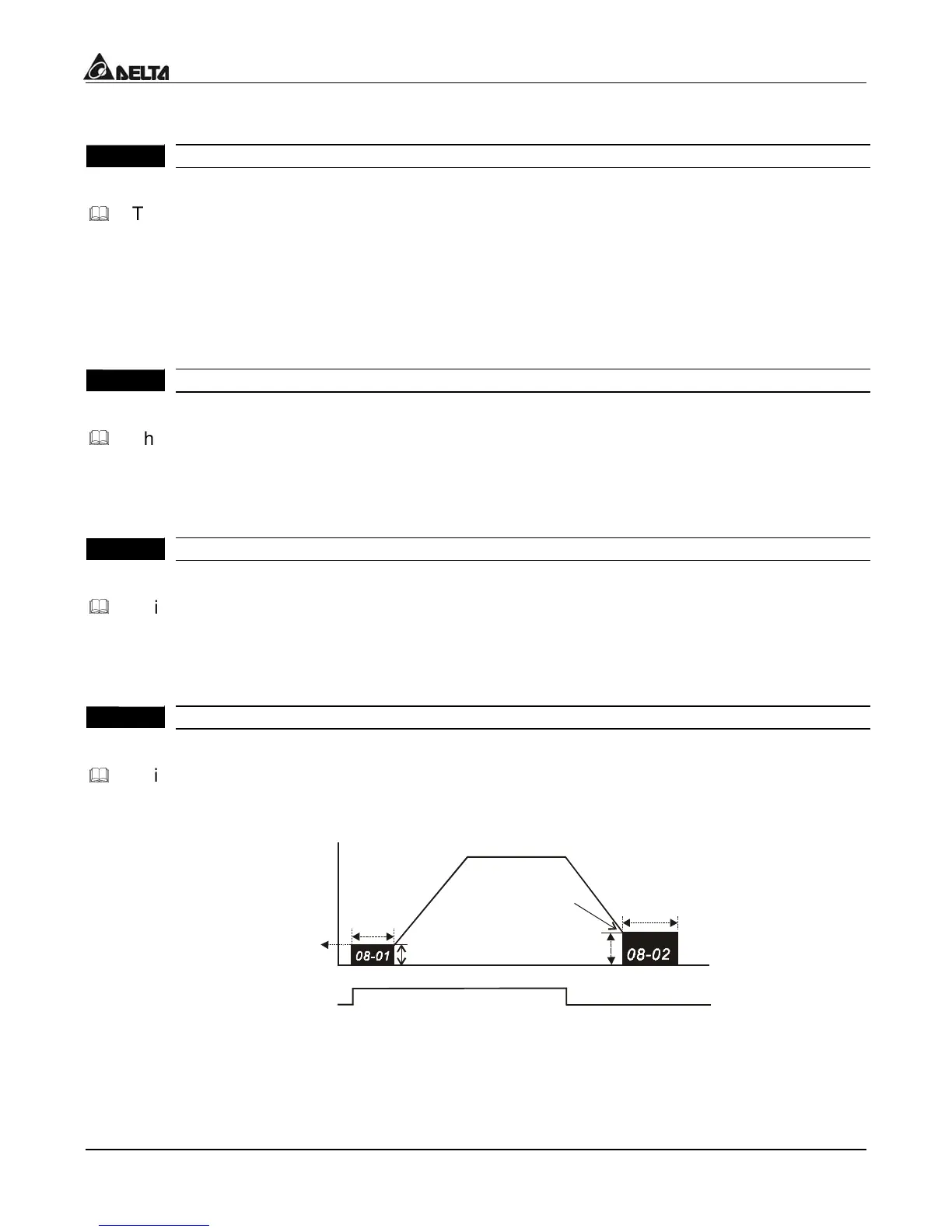
8 - 01
C Braking Time during Start-up
actory Setting: d 0.0
Settings d 0.0 to d 60.0 sec Unit: 0.1sec
This parameter determines the duration of time that the DC Braking Current will be
applied to the motor during the AC drive start-up. DC Braking will be applied for the
time set in this parameter until the Minimum Frequency is reached during acceleration.
8 - 02
C Braking Time during Stopping
actory Setting: d 0.0
Settings d 0.0 to d 60.0 sec Unit: 0.1 sec
This parameter determines the duration of time that the DC braking voltage will be
applied to the motor during stopping. If stopping with DC Braking is desired, then
Pr.2-02 must be set to RAMP stop (d 0).
8 - 03
tart-Point for DC Braking Factory Setting: d 0
Settings d 0.0 to d 400Hz Unit: 0.1Hz
This parameter determines the frequency when DC Braking will begin during
deceleration.
NOTE: 1. DC Braking during Start-up is used for loads that may move before AC drive
starts, such as fans and pumps. These loads may also be moving in the wrong
direction. Under such circumstances, DC Braking can be executed to hold the
load in position before applying a forward motion.

 Loading...


