VFD-L Series
DELTA ELECTRONICS, INC. ALL RIGHTS RESERVED
d16, d17 PLC Function Control:
Parameter value d16 programs Multi-Function Input Terminal: M1 (Pr.4-04), M2 (Pr.4-05)
or M3 (Pr.4-06) to enable the AC drive internal PLC program. Parameter value d17
programs an input terminal to pause the PLC program.
Note: Pr.5-00 to Pr.5-08 define the PLC program.
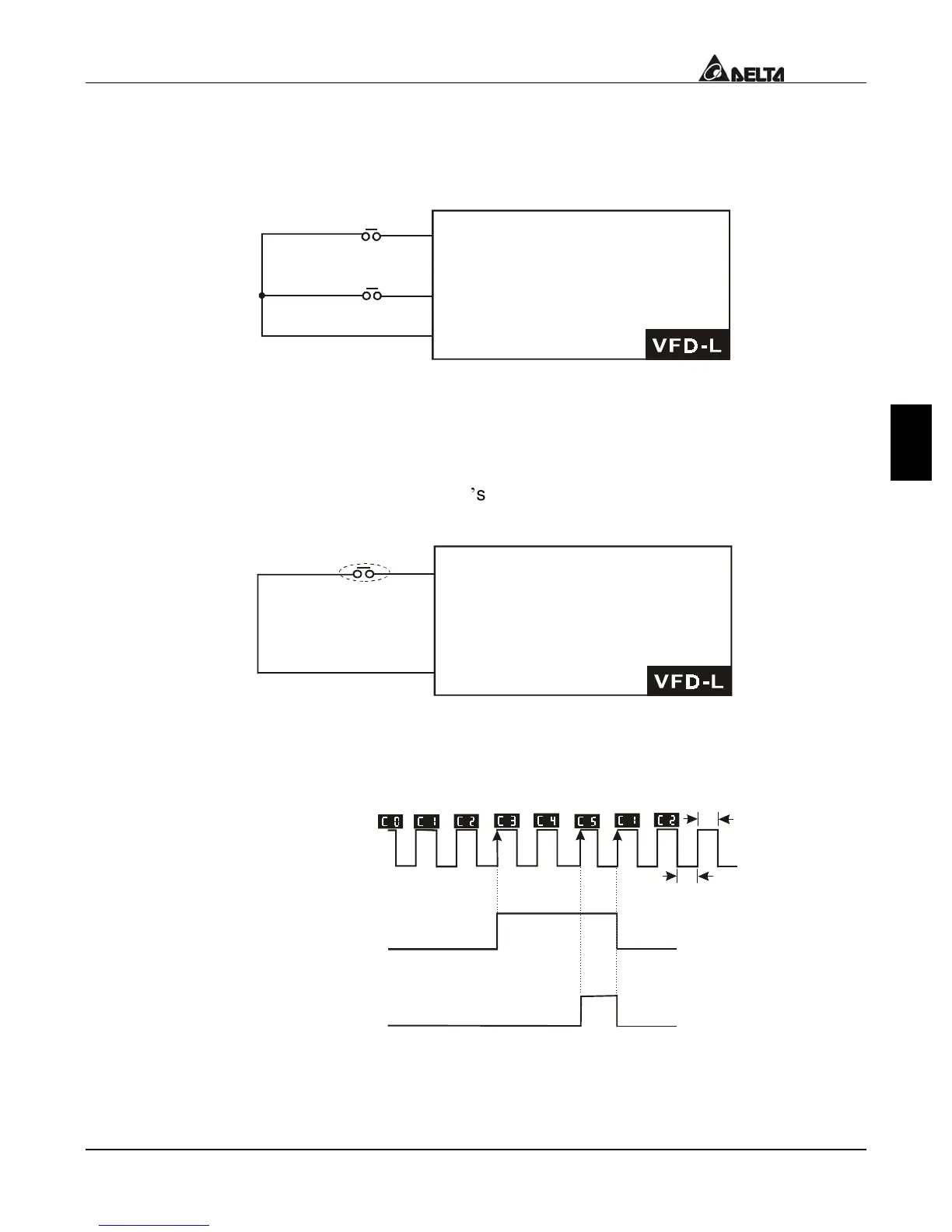
d18 Counter Trigger:
Parameter value d18 programs Multi-Function Input Terminal: M1 (Pr.4-04), M2 (Pr.4-05)
or M3 (Pr.4-06) to increase the AC drive
s internal counter. When an input is received,
the counter is increased by 1.
Mx counter value increase by
Note:The Counter Trigger input can be connected to an external Pulse Signal Generator
to count a processing step or unit of material. See the diagram below.
Multi-function input terminal
Signal output with Pr.3-02
counter value is attained.
Signal output with Pr.3-01
counter value is attained.

 Loading...


