EasyManuals Logo

Delta VFD-L Series User Manual

Delta VFD-L Series
88 pages
To Next Page IconTo Next Page
To Previous Page IconTo Previous Page
Page #42 background imageLoading...
Page #42 background image
VFD-L Series
DELTA ELECTRONICS, INC. ALL RIGHTS RESERVED
5-24
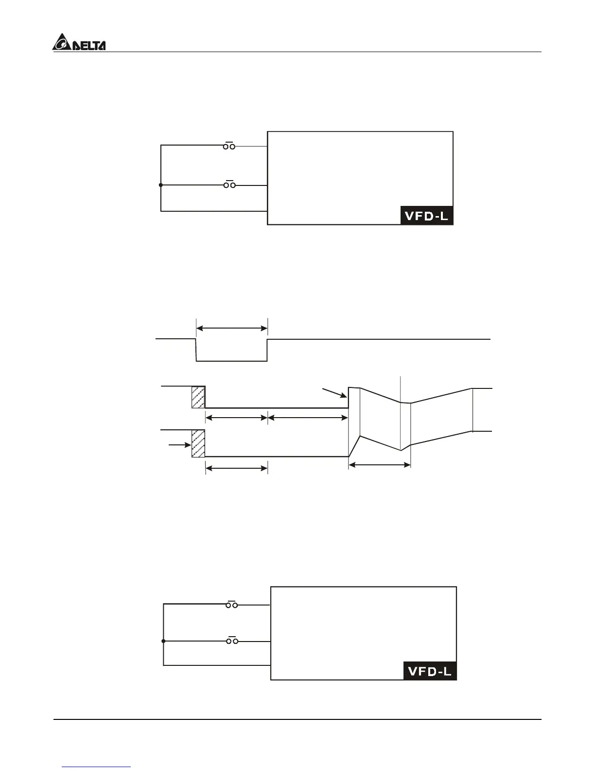
d12, d13 External Base Block:
Parameter values d12, d13 program Multi-Function Input Terminals: M1 (Pr.4-04), M2
(Pr.4-05) or M3 (Pr.4-06) for external Base Block control. Value d12 is for normally open
(N.O.) input, and value d13 is for a normally closed (N.C.) input.
GND
B.B.(N.O.)
setting by d12
B.B.(N.C.)
setting by d13
Mx "Close": Operation available.
Mx "Open":Operation available.
Note:
When a Base-Block signal is received, the AC drive will stop all output and the motor
will free run. When base block control is deactivated, the AC drive will start its speed
search function and synchronize with the motor speed, and then accelerate to
Master Frequency.
External
base-block
signal
Output
frequency
Output
voltage
Capacitor
discharge
Allowable max. power loss time
Speed search starts with the
reference value
Low voltage
Pr.8-06
Min. base-block time
Low voltage
Speed search operation
Pr.8-04=d1
Speed synchronization
detection
d14, d15 Increase/Decrease Master Frequency:
Parameter values d14, d15 program the Multi-Function Input Terminals: M1 (Pr.4-04), M2
(Pr.4-05) or M3 (Pr.4-06) to incrementally increase/ decrease the Master Frequency each
time an input is received.
GND
setting by d14
setting by d15
Mx "Close": Freq. will increase
by one unit.
Mx "Open":Freq. will decrease
by one unit.
UP
DOWN

Table of Contents

Other manuals for Delta VFD-L Series

Questions and Answers:

Question and Answer IconNeed help?

Do you have a question about the Delta VFD-L Series and is the answer not in the manual?

Delta VFD-L Series Specifications

General IconGeneral
Control MethodV/F Control
Output Voltage0 to Input Voltage
Cooling MethodFan Cooling
Enclosure RatingIP20
Overload Capacity150% for 60 seconds
ProtectionOver-voltage, Over-current, Overheat, Under-voltage, Short circuit
Braking UnitBuilt-in
Operating Temperature-10°C to 50°C (14°F to 122°F)
Digital Inputs5 programmable digital inputs
Analog Input0-10V, 4-20mA
Communication InterfaceRS-485 (Modbus)
Storage Temperature-20°C to 60°C (-4°F to 140°F)
Humidity90% RH, non-condensing
AltitudeUp to 1000m without derating
Input Voltage200-240V, 380-480V

Related product manuals