VFD-L Series
DELTA ELECTRONICS, INC. ALL RIGHTS RESERVED
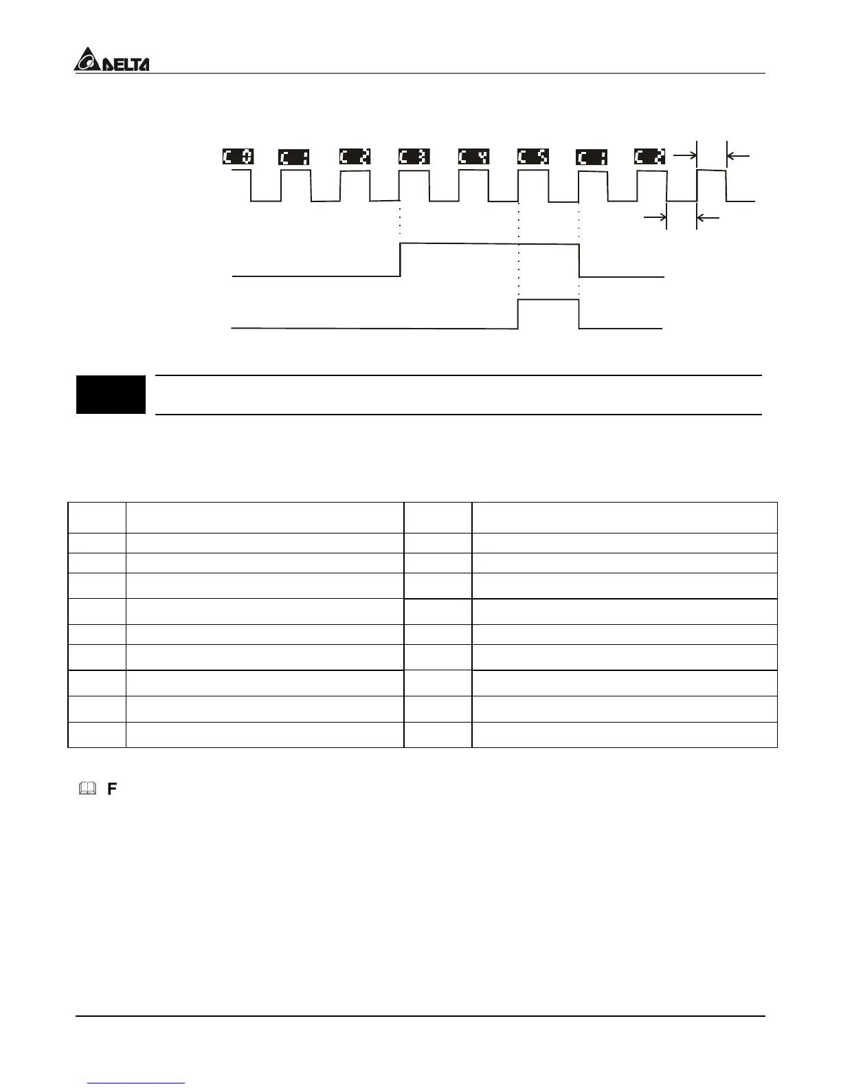
The timing diagram is shown below:
Multi-function Input Terminal
The width of trigger signal
NOTE: To display counter value set Pr.0-04=1
3 – 03
ulti-function
relay output)
actory Setting: d 8
Settings d 0 to d 16
Function Table List:
ettin
Function Setting
Function
d 0
ot used d 9
esired Frequency Attained
d 1
C Drive Operational d 10
LC Program Running
d 2
aximum Output Frequency Attaine
d 11
LC Program Step Completed
d 3
ero speed d 12
LC Program Completed
d 4
ver-Torque detection d 13
LC Operation Paused
d 5
ase-Block (B.B.) Indication
d 14
erminal Count Value Attained
d 6
ow-Voltage Indication
d 15
reliminary Counter Value Attained
d 7
C Drive Operation Mode d 16
eady State Indicator
d 8
ault Indication
Function Explanations:
d 0 Not Used.
d 1 AC drive operational:
the output of output terminal will be activated when there is an
output from the drive.
d 2 Maximum Output Frequency Attained:
the output will be activated when the AC drive
attains Maximum Output Frequency.

 Loading...


