VFD-L Series
DELTA ELECTRONICS, INC. ALL RIGHTS RESERVED
0 - 04
ontent of User Defined Unit
actory Setting: d 0
Settings d 0 Display the user-defined unit (u)
d 1 Display the counter value (C)
d 2 Display the content of PLC time (1 – tt)
d 3 Display the DC BUS voltage (U)
d 4 Display the output voltage (E)
This parameter can be set during operation.
Note: Display the user-defined unit, where unit = H
0 - 05
ser Defined Coefficient K
actory Setting: d 1.0
Settings d 0.1 to d 160 Unit: 0.1
This parameter can be set during operation.
The coefficient K determines the multiplying factor for the user-defined unit.
The display value is calculated as follows:
Display value =(output frequency x K)
The display window is only capable of showing three digits, yet you could use Pr.0-05 to
create larger numbers. The display windows uses decimal points to signify numbers up
to five digits as illustrated in the next page:
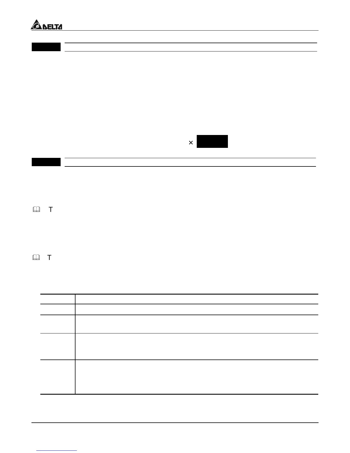
Display
Number Represented
999
he absence of a decimal point indicates a three –digit integer.
99.9
signal decimal point between the middle and the right-most numbers is a tru
ecimal point; it separates ones and tenths as in “30.5” (thirty and one-half).
999.
single decimal point after the fight-most numbers is not a true decimal point;
nstead it indicates that a zero follows the right-most number. For example,
he number 1230 would be display as “123.”
99.9.
wo decimal points (one between the middle and the right-most numbers, and
ne after the right-most number) are not true decimal points; instead they
ndicate that two zeros follow the right-most number. For example, the
umber 34500 would be display as “34.5.”.

 Loading...


