VFD-L Series
DELTA ELECTRONICS, INC. ALL RIGHTS RESERVED
Group 2: Operation Method Parameters
2 – 00
ource of Frequency Command
Factory Setting: d 0
Settings d 0 Master Frequency input determined by digital keypad.
d 1 Master Frequency determined by analog signal DC 0V-10V
(external terminal AVI).
d 2 Master Frequency determined by analog signal DC 4mA -
20mA (external terminal AVI).
d 3 Master Frequency determined by Potentiometer on the
digital keypad.
d 4 Master Frequency operated by RS-485 serial
communication interface.
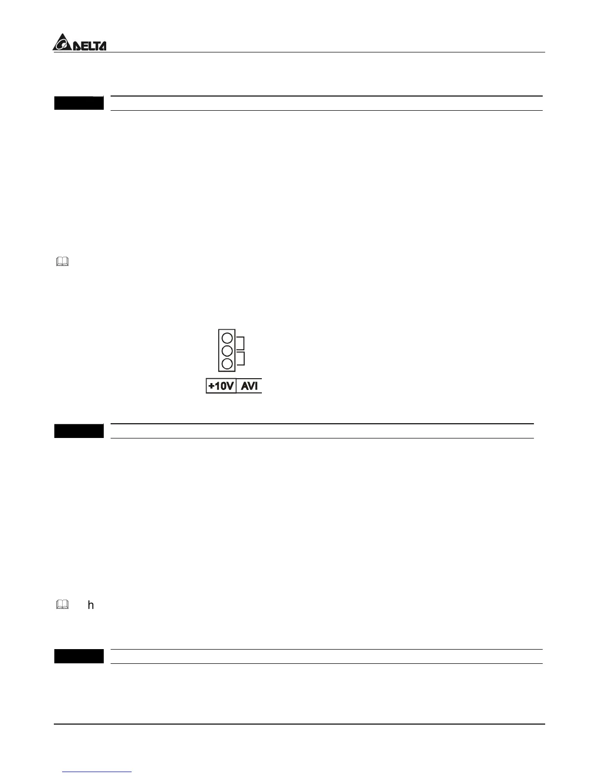
This parameter sets the Frequency Command Source of the AC drive.
If the Frequency Command Source is external (DC 0 to +10V or 4 to 20mA), please
select DC voltage signal or current signal.
Voltage signal input(0-10V)
Current signal input(4-20mA)
2 - 01
ource of Operation Command
actory Setting: d 0
Settings d 0 Controlled by the keypad
d 1 Controlled by the external terminals, keypad STOP
enabled.
d 2 Controlled by the external terminals, keypad STOP
disabled.
d 3 Controlled by the RS-485 communication interface,
keypad STOP enabled.
d 4 Controlled by the RS-485 communication interface,
keypad STOP disabled.
When the AC drive is controlled by an external source, please refer to parameter group 4
for detailed explanations on related parameter settings.
2 - 02
top Method
actory Setting: d 0
Settings d 0 Ramp stop
d 1 Coast stop

 Loading...


