VFD-L Series
DELTA ELECTRONICS, INC. ALL RIGHTS RESERVED
3.2
Terminal Explanations
Terminal Symbol Explanation of Terminal Function
R/L1, S/L2, T/L3 AC line input terminals
U/T1, V/T2, W/T3 AC drive output terminals motor connections
Earth Ground
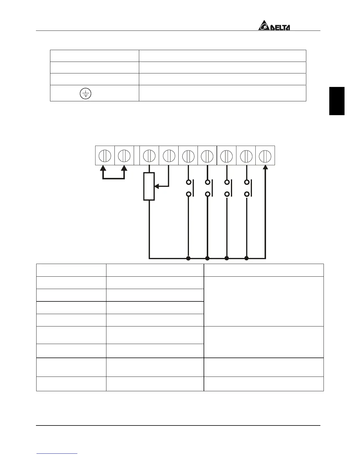
3.3 Control Terminals Explanations
(
1
2
0
V
A
C
/
D
C
2
8
V
3
A
)
M
u
l
t
i
-
f
u
n
c
t
i
o
n
i
n
d
i
c
a
t
i
o
n
o
u
t
p
u
t
c
o
n
t
a
c
t
P
o
w
e
r
f
o
r
s
p
e
e
d
s
e
t
t
i
n
g
A
n
a
l
o
g
V
o
l
t
a
g
e
,
c
u
r
r
e
n
t
f
r
e
q
u
e
n
c
y
c
o
m
m
a
n
d
M
u
l
t
i
-
f
u
n
c
t
i
o
n
a
s
s
i
s
t
a
n
t
t
e
r
m
i
n
a
l
C
o
m
m
o
n
s
i
g
n
a
l
M
u
l
t
i
-
f
u
n
c
t
i
o
n
i
n
p
u
t
s
e
l
e
c
t
i
o
n
1
M
u
l
t
i
-
f
u
n
c
t
i
o
n
i
n
p
u
t
s
e
l
e
c
t
i
o
n
2
M
u
l
t
i
-
f
u
n
c
t
i
o
n
i
n
p
u
t
s
e
l
e
c
t
i
o
n
3
Terminal Symbols Terminal Functions Factory Settings
MI0
Multi-function Input 0
MI1
Multi-function Input 1
MI2
Multi-function Input 2
MI3
Multi-function Input 3
Refer to Pr.04-04 to Pr.04-06
Multi-function Input Terminals
RA
Multi-function Relay output
(N.O.) a
RC
Multi-function Relay common
120Vac, 3A
24Vdc, 3A
Refer to Pr.03-03
+10V
Potentiometer power source
+10V 20mA
AVI Analog voltage/ Input current
0 to +10V / 4 to 20mA
* Control signal wiring size: 22-24 AWG (0.3-0.2 mm
2
).

 Loading...


