EasyManuals Logo

Delta VFD-L Series User Manual

Delta VFD-L Series
88 pages
To Next Page IconTo Next Page
To Previous Page IconTo Previous Page
Page #31 background imageLoading...
Page #31 background image
5
VFD-L Series
DELTA ELECTRONICS, INC. ALL RIGHTS RESERVED
5-13
Group 3: Output Function Parameters
3 - 00
D
esired Frequency Attained
F
actory Setting: d 1.0
Settings d 1.0 to d 400 Hz Unit: 0.1Hz
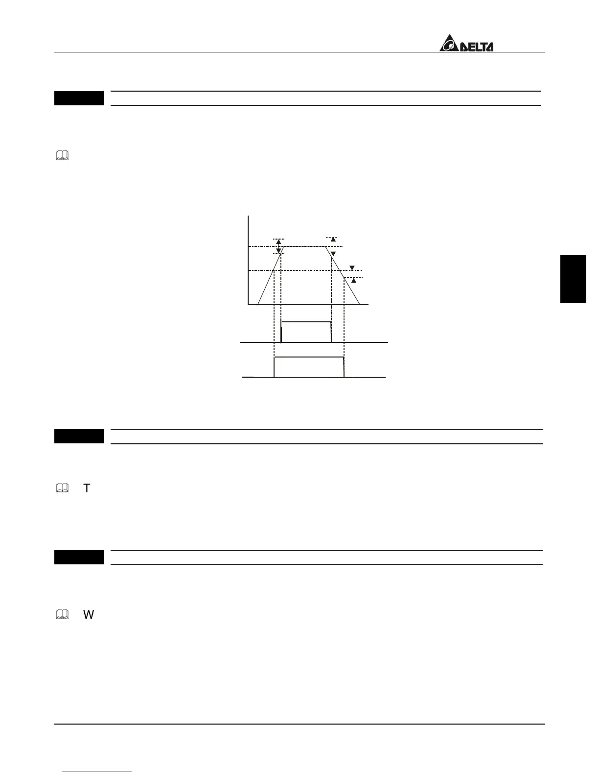
If a Multi-function output terminal is set to function as Desired Frequency Attained
(Pr.3-03=d9), then the output will be activated when the programmed frequency is
attained.
Desired Freq.
Detection
range
-2Hz
Detection range
+
-
4Hz
Detection range
+
-
2Hz
Time
Freq.
Max. Output
Freq.
Pr.3-02
ON
ON
OFF
OFF
OFF
OFF
Preset Freq.
Attained
indication
Pr.3-03
Desired Freq.
Attained
Indication
Pr.3-03
Desired Freq. Attained & Preset Freq. Attained
3 – 01
T
erminal Count Value
F
actory Setting: d 0
Settings d 0 to d 999
The parameter determines the value of the internal counter. The internal counter can be
triggered by the external terminal (Pr.4-4 to Pr.4-6, d18). Upon completion of counting,
the specified output terminal will be activated. (Pr.3-03=d14).
3 – 02
P
reliminary Count Value
F
actory Setting: d 0
Settings d 0 to d 999
When the counter value is counted up from “1” to the setting value of this parameter, the
corresponding multi-function output terminal will be closed, when sets d15 as desired
value attained setting. The application can be that closing the multi-function output
terminal makes the AC drive operate at low speed until stop before the counting value is
going to be attained.

Table of Contents

Other manuals for Delta VFD-L Series

Questions and Answers:

Question and Answer IconNeed help?

Do you have a question about the Delta VFD-L Series and is the answer not in the manual?

Delta VFD-L Series Specifications

General IconGeneral
Control MethodV/F Control
Output Voltage0 to Input Voltage
Cooling MethodFan Cooling
Enclosure RatingIP20
Overload Capacity150% for 60 seconds
ProtectionOver-voltage, Over-current, Overheat, Under-voltage, Short circuit
Braking UnitBuilt-in
Operating Temperature-10°C to 50°C (14°F to 122°F)
Digital Inputs5 programmable digital inputs
Analog Input0-10V, 4-20mA
Communication InterfaceRS-485 (Modbus)
Storage Temperature-20°C to 60°C (-4°F to 140°F)
Humidity90% RH, non-condensing
AltitudeUp to 1000m without derating
Input Voltage200-240V, 380-480V

Related product manuals