EasyManuals Logo

Delta VFD-L Series User Manual

Delta VFD-L Series
88 pages
To Next Page IconTo Next Page
To Previous Page IconTo Previous Page
Page #36 background imageLoading...
Page #36 background image
VFD-L Series
DELTA ELECTRONICS, INC. ALL RIGHTS RESERVED
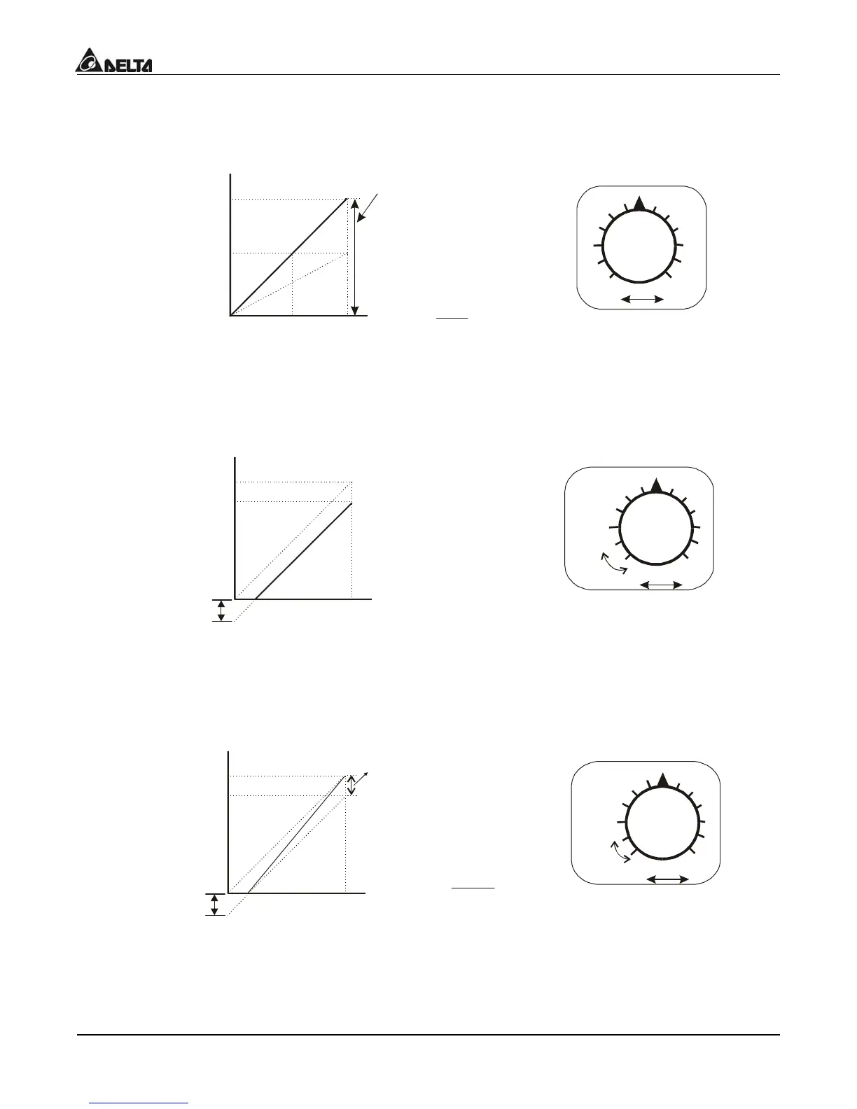
5-18
Example 4:
This example shows a potentiometer range of 0 to 5 Volts.
Hz
0V
5V
30
0
60
Potentiometer Scale
Parameter Settings
Pr.1-00=60Hz--Max. output Freq.
Pr.4-00=0Hz--Potentiometer bias freq.
Pr.4-01=0 -- bias polarity
Pr.4-02=200% -- pot. freq. gain
Pr.4-03=0 -- pot. REV motion enable
Max.
Output
Freq.
60Hz
Pr.1-00
0Hz
0V
5V
Calculation of gain
Pr.4-02= (
10V
5V
)x100%
30Hz
Gain adjustment
Example 5:
In this example a 1 volt negative bias is used. In a noise environment, it is advantageous to
use negative bias to provide a noise margin (1V in this example).
Hz
0V
10V
24
0
54
Potentiometer Scale
Max.
Output
Freq.
60Hz
Pr.1-00
0Hz
0V
10V
Parameter Settings
Pr.1-00=60Hz--Max. output Freq.
Pr.4-00=6Hz--Potentiometer bias freq.
Pr.4-01=1 -- bias polarity
Pr.4-02=100% -- pot. freq. gain
Pr.4-03=0 -- pot. Rev. motion enable
Ne gative
bias 6Hz
1V
54Hz
It's 0Hz
within
this
range.
Example 6:
In this example, a negative bias is used to provide a noise margin. Also a potentiometer
frequency gain is used to allow the Maximum Output Frequency to be reached.
Hz
0V
10V
27
0
60
Potentiometer Scale
Max.
Output
Freq.
60Hz
Pr.1-00
0Hz
0V
10V
Parameter Settings
Pr.1-00=60Hz--Max. output Freq.
Pr.4-00=6Hz--Potentiometer bias freq.
Pr.4-01=1 -- bias polarity
Pr.4-02=110% -- pot. freq. gain
Pr.4-03=0 -- pot. Rev. motion enable
Ne gative
bias 6Hz
1V
It's 0Hz
within
this
range.
Bias adjustment
Calculation of gain
Pr.4-03=(1+
Pr.4-00
Pr.1-00
)x100%

Table of Contents

Other manuals for Delta VFD-L Series

Questions and Answers:

Question and Answer IconNeed help?

Do you have a question about the Delta VFD-L Series and is the answer not in the manual?

Delta VFD-L Series Specifications

General IconGeneral
Control MethodV/F Control
Output Voltage0 to Input Voltage
Cooling MethodFan Cooling
Enclosure RatingIP20
Overload Capacity150% for 60 seconds
ProtectionOver-voltage, Over-current, Overheat, Under-voltage, Short circuit
Braking UnitBuilt-in
Operating Temperature-10°C to 50°C (14°F to 122°F)
Digital Inputs5 programmable digital inputs
Analog Input0-10V, 4-20mA
Communication InterfaceRS-485 (Modbus)
Storage Temperature-20°C to 60°C (-4°F to 140°F)
Humidity90% RH, non-condensing
AltitudeUp to 1000m without derating
Input Voltage200-240V, 380-480V

Related product manuals