XR500 Series Canadian Programming Guide Digital Monitoring Products
1
INTRODUCTION
Introduction
1.1 Before you Begin
This guide provides programming information for the DMP XR500, XR500N, and XR500E Command
Processor™ Panel. After this Introduction, the remaining sections describe the functions of each
programming menu item along with the available options. Before starting to program, we recommend
that you read through the contents of this guide. The information contained here allows you to quickly
learn the programming options and operational capabilities of the XR500, XR500N, and XR500E panels.
In addition to this guide, you should also read and be familiar with the following XR500 Series Canadian
documents:
• XR500SeriesCanadianInstallationGuide(LT-0681CAN)
• XR500SeriesCanadianProgrammingSheet(LT-0678CAN)
• XR100/XR500CanadianSecurityCommand
®
User’sGuide(LT-0683CAN)
Internal Programmer
Thepanelcontainsallofitsprogramminginformationinanon-boardprocessoranddoesnotrequirean
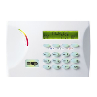
externalprogrammer.Youcanperformallprogrammingtasksthrougha32-characterDMPalphanumeric
keypad set to address one.
Programming Information Sheet
Included with each panel are the Programming Information Sheets. These list the various programming
prompts and available options for programming the panel. Before starting to program, we recommend you
completelyllouteachsheetwiththeprogrammingoptionsyouintendtoenterintothepanel.
Having completed programming sheets available before entering data helps prevent errors and can shorten
the time you spend programming. Completed sheets also provide you with an accurate panel program
recordyoucankeeponleforfuturesystemserviceorexpansion.TheremainderofthisIntroduction
provides instructions for starting and ending a programming session using the alphanumeric keypad.
1.2 Getting Started
Ground Yourself Before Handling the Panel! Touch any grounded metal, such as the enclosure, before
touching the panel to discharge static.
Remove All Power From the Panel! Remove all AC and Battery power from the panel before installing or
connecting any modules, cards, or wires to the panel.
Before starting to program the XR500 Series Canadian panel, make sure the panel is properly grounded and
AC and battery power is applied to the appropriate panel terminals. All wiring connections and grounding
instructionsaredetailedintheXR500SeriesCanadianInstallationGuide(LT-0681CAN).
Program from any Keypad Address or Wireless Keypad
Program from any Keypad Address or Wireless Keypad
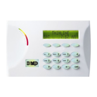
YoucanprogramtheXR500panelfromany32-characterwirelesskeypadorhardwiredkeypadconnected
tothepanel’skeypaddatabus.SeetheXR500InstallationGuideforkeypadaddressingandinstallation
information for hardwired keypads.
Wireless Keypads can be used for panel programming after being programmed in the panel manually or by
using the Wireless Keypad Association operation.
Toenableassociationoperationinthekeypad,accesstheInstallerOptionsMenu(3577(INST))and
selectRFSurvey.ThekeypadlogoLEDsturnonReduntilassociationissuccessful.
To enable association operation in the XR500 panel, reset the panel 3 times within 12 seconds. Allow
thepanel’skeypadbusTransmit/ReceiveLEDstoturnbackonbetweeneachreset.
For60secondsthepanellistensforwirelesskeypadsthatareintheInstallerOptionsMenuandhave
notbeenprogrammed,orassociatedintoanotherpanel.Thosekeypadsareassignedtotherst
open device position automatically based upon
the order in which they are detected. The
keypadlogoturnsGreentoindicateithasbeen
associated with the panel. See the 9000 Series
WirelessKeypadInstallationGuide(LT-1107)for
additional information.
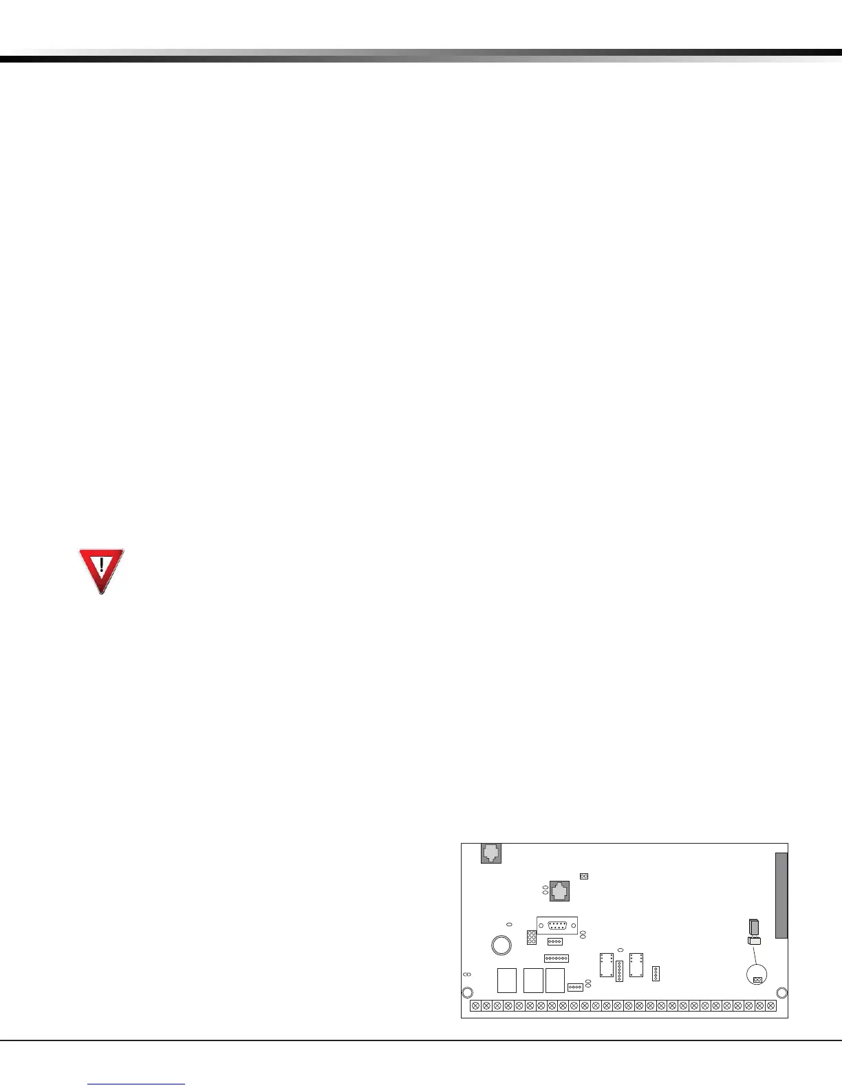
Accessing the Programmer
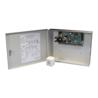
1. Momentarily place the Reset jumper over both
oftheJ16pinstoresetthepanel.
2. Enterthecode6653(PROG)andpress
COMMAND.
3. The keypad displays: PROGRAMMER.
Figure 1: XR500 Series Canadian Panel Showing Reset
J6
Interface
Card
Expansion
Connector
To enable Wireless Keypad
Association operation:
Reset panel 3 times within
12 seconds.
To access the programmer:
Momentarily place the
Reset jumper over both of
the J16 pins to reset the
panel.
AC
12345678 10 11 12 13 14 15 16 17 18 19
02122 23 24 25 26 27 28
+B BELL GND SMK GNDRED YEL GRN BLK Z1 Z2 Z3 Z4 Z5 Z6 Z7 Z8 Z9+ Z9– Z10+ Z10–AC –B GND GND GNDGND
K6 K7
Output 1 Output 2
J3
Phone Line
J10
J22
LX-Bus
Battery
Start
J23
J21
RS-232
Power
LED
J8
PROG
J4
Tamper
J16
Reset
Out1 Out2
Outputs 3-6
J11
3
4
5
6
J2
J1
Ethernet
R
L
X
OVC
Link LED
Activity LED
 Loading...