1 XTLtouch Series Programming Guide | Digital Monitoring Products
FOR YOUR INFORMATION
Before programming the XTLtouch™, we recommend you read through the contents of this guide. Use this information
to learn the programming options and operational capabilities of the XTLtouch. The XTLtouch contains all of its
programming information in an on-board processor and does not require an external programmer. In addition to this
guide, you should also be familiar with the following XTLtouch documents:
▶ XTLtouch Series Installation Guide (LT-1788)
▶ XTLtouch Series Programming Sheet (LT-1790)
▶ XTLtouch Series Fast Programming Sheet (LT-1790F)
▶ XTLtouch Series System User Guide (LT-1791)
XTL Series panels with Version 194 firmware and higher ship with a unique four-digit default master code. This master
code is generated using an algorithm based o of the last four digits of the serial number to ensure that it cannot be
duplicated. This code can be modified or deleted. In order to revert back to the default code 99, use the initialize code
option found in panel programming.
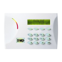
Wireless Keypad Association
Associate up to seven DMP 9000 Series Thinline Keypads or 9800 Series Graphic Touchscreen Keypads with the
XTLtouch. It’s important to keep the XTLtouch as Device 1 when associating additional keypads.
System Types
The XTLtouch can be programmed to operate as any of the following system types:
▶ All/Perimeter: Provides one perimeter area and one interior area.
▶ Home/Sleep/Away: Provides one perimeter, one interior, and one bedroom area. The bedroom area provides for
any protection devices the user wants disarmed during their sleeping hours and armed in the Away mode.
▶ Area: Provides up to six areas of protection that can be independently armed or disarmed.
Compliance Instructions
For applications that must conform to a local authority’s installation standard or a National Recognized Testing
Laboratory certificated system, please see the Listed Compliance Specifications section near the end of this guide for
additional instructions.
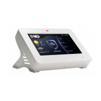
LED Operation
The LED at the top of the XTLtouch indicates the
power and armed status of the panel. Depending
on the operation, the LED displays in red or blue as
listed in the table.
Reset Button
The RESET button is located on the back of the unit in the lower left corner under the backplate and is used to reset the
XTLtouch panel. To reset the panel prior to reprogramming, press the RESET button without powering down the system.
After resetting the panel, begin programming within 30 minutes. If you wait longer than 30 minutes, you must reset the
panel again.
COLOR AND ACTIVITY OPERATION
Blue steady Panel is disarmed, primary power is okay, battery is okay
Blue blinking Panel is disarmed, primary power is okay, battery is faulted
No light Panel is disarmed, primary power is faulted, battery is okay
Red steady Panel is armed, primary power is okay, battery is okay
Red/blue alternate Panel is armed, primary power is okay, battery is faulted
Red blinking Panel is armed, primary power is faulted, battery is okay