Dobot CR Series User Guide
Issue V1.1 (2023-04-27) User Guide Copyright © Yuejiang Technology Co., Ltd.
50
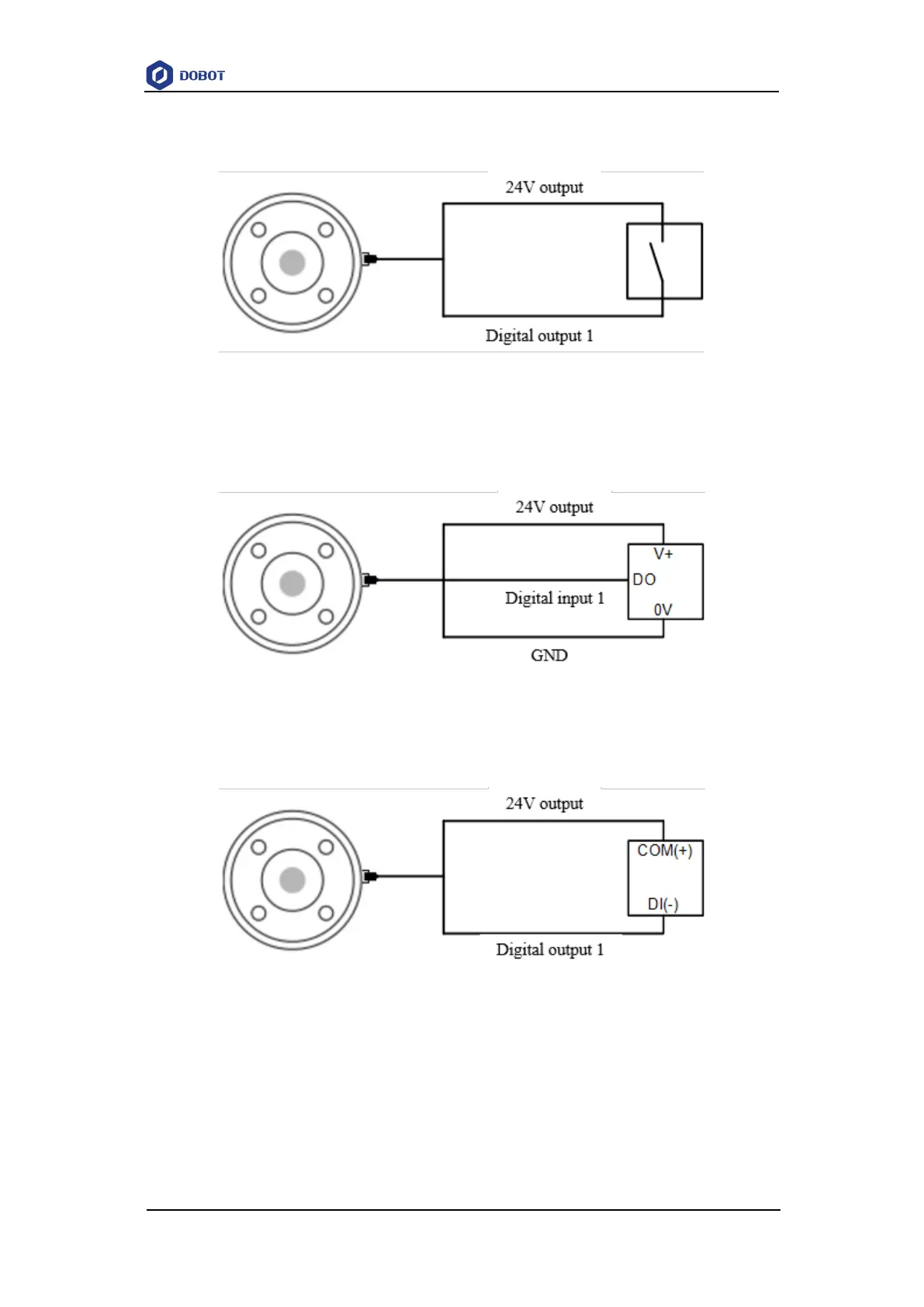
When using external simple switching circuit as the DI input source, the wiring is shown in
Figure 6.15.
Figure 6.15 End DI wiring (simple switch)
When using the DO terminal of an external device as the DI input source, the wiring is shown
in Figure 6.16, which takes a PNP-type DO without power supply as an example. If the DO has its
own power supply, you do not need to connect the 24V cable.
Figure 6.16 End DI wiring (PNP type DO)
The digital output of the end I/O is NPN type, with the single output current no more than
400mA and the total output current no more than 400mA. The wiring is shown as follows.
Figure 6.17 End DO wiring
Analog input
The wiring of analog I/O connected to the tested object is shown in Figure 6.18.