Install a guide bar into a bolt hole on the crank shaft,
and lift the flywheel to align the dowel pin with the pin
hole on the flywheel for temporary assembly operation.
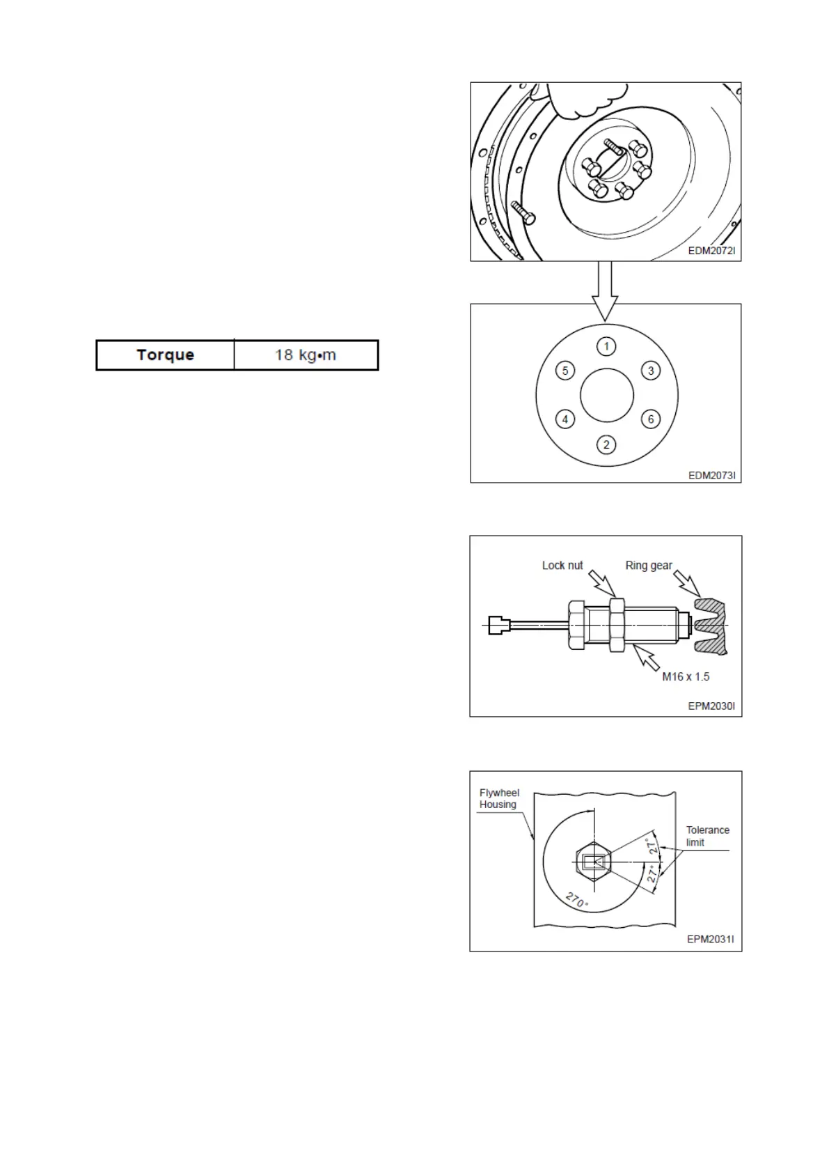
Coat the adhesive (#271 Loctite) over the assembling
bolts and install bolts in the remaining holes. After that
take out the guide bar, then install a bolt in the hole
where the guide bar had been inserted.
According to the order of tightening tighten the fixing
bolts using a torque wrench in a diagonal sequence to
specified torque.
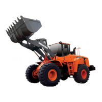
3.3.9 Magnetic pick-up sensor
Move the lock nut to hexagonal side of sensor
completely.
Rotate (Clockwise) the pick-up sensor on fly wheel
housing, until the end of it reach on fly wheel ring gear.
Then rotate (Counter clockwise) the pick-up sensor for
270° (gap 1.0 mm) and fix lock nut.
Tolerance limit is 27°. (gap L 0.1 mm)
SPC000006 5ton Diesel Engine
Page 68