Install components
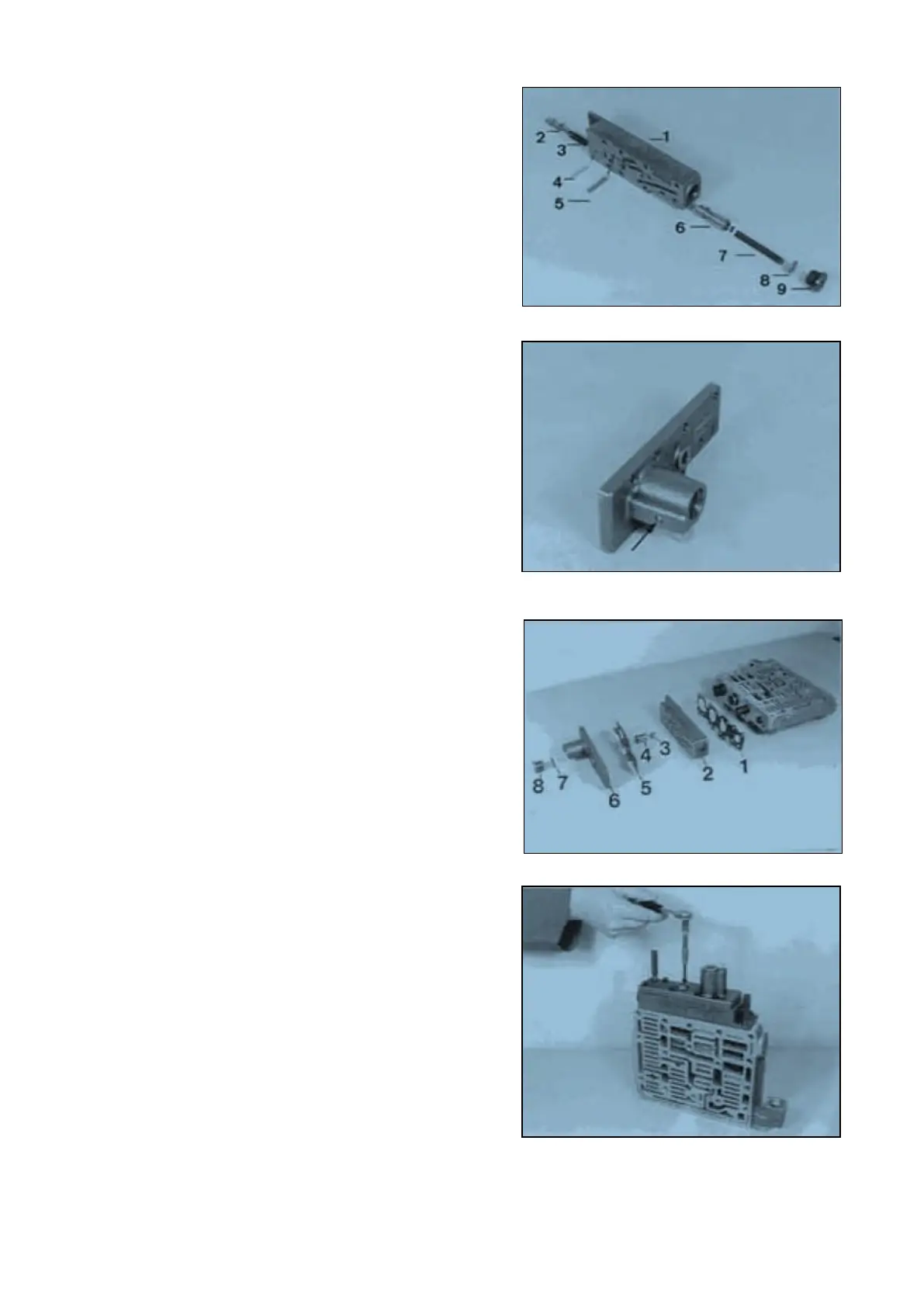
1 = Intermediate plate
2 = Valve
3 = Compression spring (L
o
= 29,90 mm)
4 = Straight pin
5 = Roller
6 = Spool
6a = Disk (s = 2,5 mm/empirical value)
7 = Spring (L
o
= 70,90 mm)
8 = Disk(s)
9 = Screw plug (mount new O-Ring)
NOTE :
Insert compression spring (3) and valve (2) in the
bore, preload and fix by means of straight pin (4) !
p3 is determined by the disk(s) 6a
(pay attention to Notes, Page 12 ... 14) !
Close the bore by means of ball (Φ 5 mm), s e e
Arrow !
Install components and fix them by means of socket
head screws and flat washers (Figure 54 and 55).
1 = Gasket
2 = Housing assembly
3 = Ring (optional)
4 = Spool
5 = Gasket
6 = Cover
7 = O-Ring
8 = Screw plug
NOTE ;
Δ t3 is determined by the ring (3)
(pay attention to Notes, Page 12 ... 14) !
Torque limit (M5/8.8) 5,5 Nm
( S ) Adjusting screws (M5) 5870 204 036
with nut
( S ) Adjusting screws (M6) 5870 204 049
with nut
SPC000007 Transmission and Torque Converter
Page 30