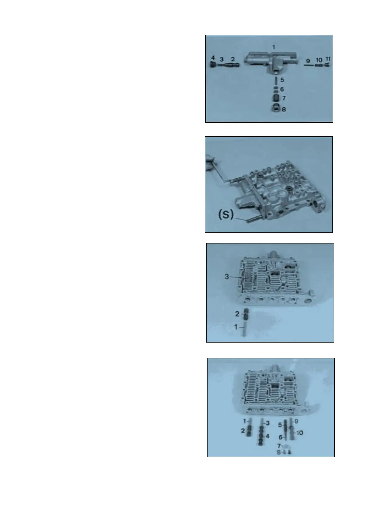
Install components ;
1 = Shift-control housing
2 = Spool
3 = Spring (L
0
= 70,90 mm)
4 = Screw plug
5 = Cylindrical roller (6 x 32 mm)
6 = Ring(s) (optional)
7 = Spool
8 = Screw plug
9 = Spring (L
0
= 70,90 mm)
10 = Spool
11 = Screw plug
NOTE ;
p3 is determined by the ring 6
(pay attention to Notes, Page 12 ... 14) !
Pay attention to the installation position of the spool
(7), bore is facing the screw plug !
Employ new O-Rings for screw plugs !
Install two adjusting screws ( S ) and assemble flat
gasket.
Pull pre-assembled pressure control valve by
means of nuts ( S ) against shoulder and fasten it
subsequently by means of socket head screws
(mount flat washers).
Torque limit (M6/8.8) 9.5 Nm
( S ) Adjusting screw (M6) 5870 204 049
with nut
Introduce spool (2) and spring (1), preload and fix
them by means of stop plate (3).
1 = Spring (L
0
= 51,30 mm)
2 = Control spool (total length = 3 9 .5 0 mm)
3 = Stop plate
Install components ;
1 = Spring (Lo =51.30 mm)
2 = Control spool (total length 39.50 mm )
3 = Spring (Lo =51.30 mm)
4 = Control spool
5 = Spool (reducing valve)
6 = Spring ( Lo = 37,10 mm)
7 = Retaining plate
8 = Socket head screws (2 pieces)
9 = Spring (Lo = 51,30 mm)
10 = Pilot spool (total length = 52,50 mm)
Transmission and Torque Converter SPC000007
Page 61