III. EXAMPLE FOR PLATE INSTALLATION
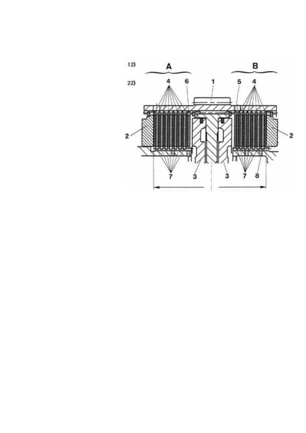
The following Draft shows the plate installation of the Clutch KV and K1 !
Ref. Draft :
A = Clutch KV
(Plate installation-No. e.g. 12)
B = Clutch KI
(Plate installation-No. e.g. 22)
1 = Plate carrier
2 = Backing plate
3 = Piston
4 = Outer plates
5 = Outer plates
(one-sided coated)
6 = Compensating plate
(Outer plate uncoated)
7 = Inner plates
8 = Compensating plate
(Inner plate)
Attention :
In principle, the arrangement of the outer and inner plates has to be carried out alternately.
Starting with the piston side, the first plate must be one double-sided coated outer plate (Standard Version).
Exception "A" :
In case of Plate installation-No. 22,31 and 41, the first plate must be one one-sided coated outer plate, and
in this case, the plate must be always installed with the uncoated side facing the piston !
Exception "B" :
In case of Plate installation-No. 12 and 13, the first plate must be one double-sided uncoated outer plate
(compensating plate).
As second plate, one coated outer plate has to be installed.
Now, pile up the inner and outer plates alternately again !
SPC000007 Transmission and Torque Converter
Page 122
Plate thicknesses
decreasing
Plate thicknesses
decreasing
Figure 58
 Loading...