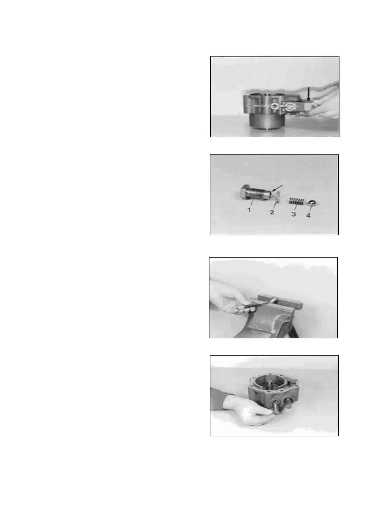
Bring shift fork, in direction of Arrow, to the upper
stop position (final drive is engaged).
In this position, the countersinking of the shift fork
must be centric to the tapped hole of the housing.
If necessary, correct by means of corresponding
shims (Figure 19) !
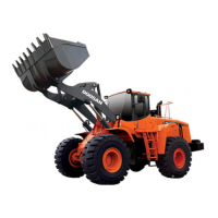
The Illustration on the left shows the components of
the locking screw.
1 = Spring bush
2 = Sealing ring
3 = Compression spring
4 = Ball
Fix the ball by indents (3 x 120°) on the end face of
the spring bush (see Arrow, Figure28).
Insert compression spring and ball in the spring
bush and preload them in a vise.
Assemble new sealing ring and install locking screw.
SPC000007 Transmission and Torque Converter
Page 186