35519
J
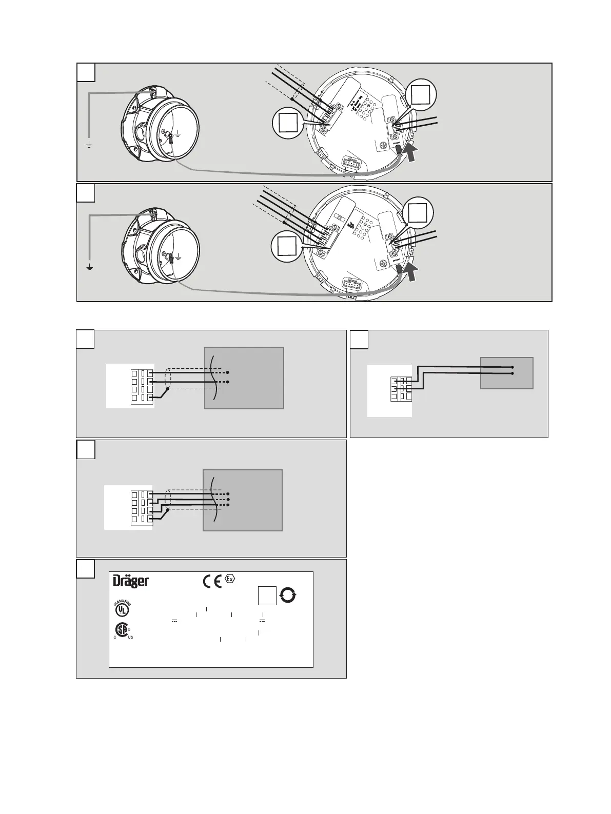
1
2
3
4
1
2
DATA A
DATA B
N.C.
Shield
PWR+
PWR-
J1
J1
L
Cable specifications
Power supply and signals: 24 - 12 AWG / 0.2 - 2.5 mm²
DATA A
DATA B
Ground
Shield
1
2
3
4
1
2
DATA A
DATA B
Ground
Shield
PWR+
PWR-
PWR+
PWR-
SCR
Power
VDC
+
-
DATA A
DATA B
N. C.
Shield
FB+ / Data A
FB- / Data B
Fieldbus FF / Profibus PA
+ / Data A
- / Data B
Ground
Modbus RTU
Fieldbus FF / Profibus PA
K
Modbus RTU
J1
K1
L
M
K1
L
Ser ial N o : XXXX- XXXX
II 2G
II 2D
0158
XTR 0XXX
9N54
Gas Detector for Use in Hazardous Locations as to
Fire, Electrical Shock and Explosion Hazards only
Class I, Div 1, Groups A,B,C,D
Class I, Zone 1, Group IIC
Polytron Xxx0
Part No: XXXXXXX
Type 4X
UL only: Class II, Div 1, Groups E,F,G
T-Code T6/T4
Supply: 10 ...30V , 0.08 ...0.15mA
Ex db IIC T6/T4 Gb
WARNING: Do not open when energized-
risk of Ignition of Harzadous Atmospheres.
AVERTISSEMENT: Lire attentivement le
manuel avant utilisation.
Dräger Safety 23560 Lübeck, Germany
Ex tb IIIC T80/130°C Db
-40°C ≤ Ta ≤ +40/+80°C
PTB 11 ATEX 1005X
IECEx PTB 11.0005X
IP6X P ≤ 5W
BVS 15 ATEX G 001X
UL only: -40°C ≤ Ta ≤ +70°C
WARNING: To reduce the risk of Ignition
of Hazardous Atmospheres, the conduit
must be sealed within 18” of the enclosure.
WARNING: Read Manual before operating.
Data
Matrix
Code
C22.2 No. 152
Relays: 5A, 30V or 230V
~
10
SAMPLE

 Loading...


