Initial Setup & Basic Operations DTG M Series Maintenance Manual
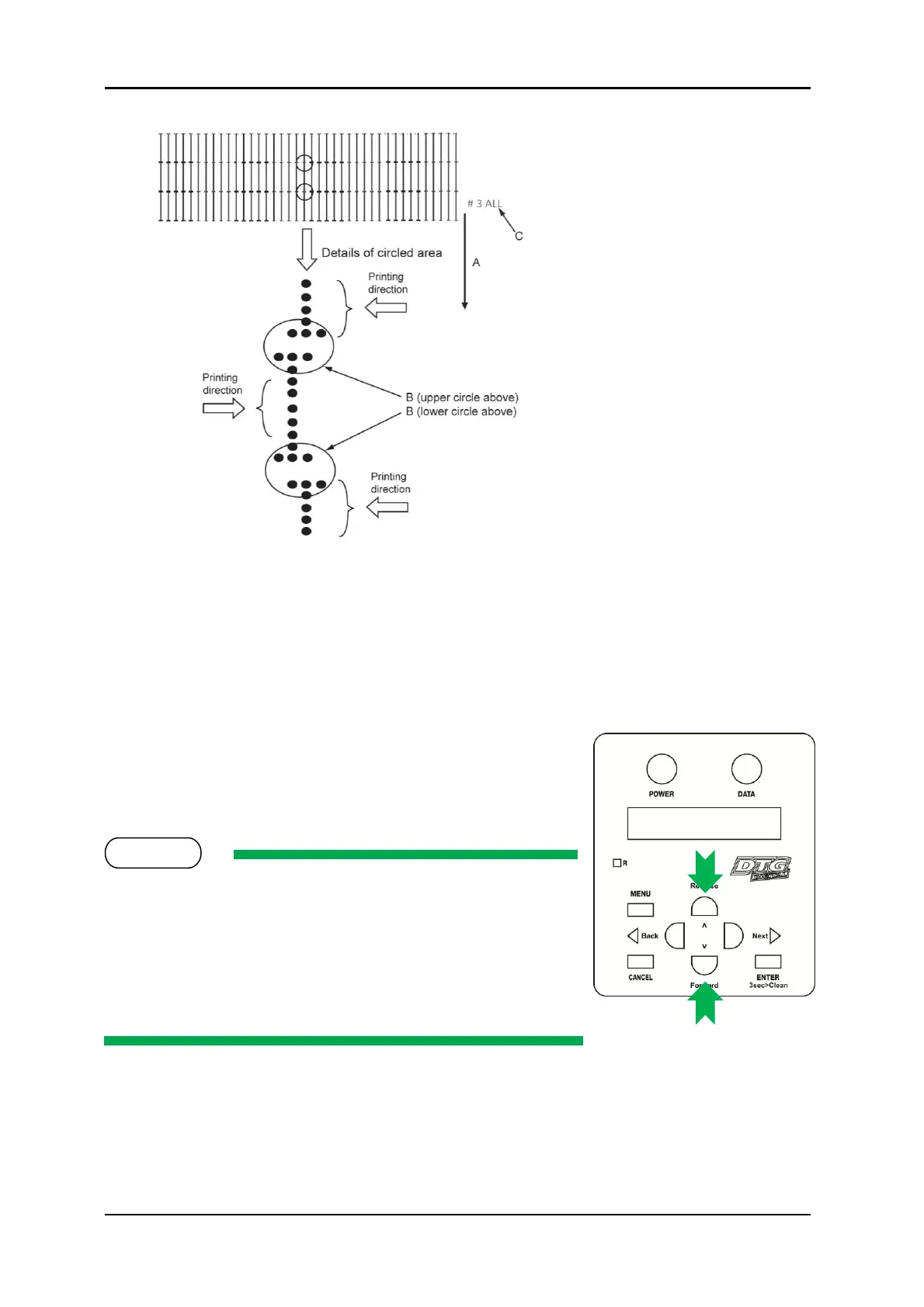
(The following shows a case for Bi-
D High 1)
A. Media feed direction
B. Adjust the setting value so that
the printed dots are aligned at this
connecting point.
C. Indicates the adjustment
pattern printed - # 3 = Bi-D High1,
# 4 = Bi-D High2
13. In the above example, the L-R (left to right) print direction dots have printed to the left of
the R-L (right to left) print direction dots.
14. The LCD will display # 3 B i D , P G 2 : X X X where XXX is a value between -400 and +400,
this is the current parameter for the Bi-D adjustment; the value that has produced the test
print just printed.
15. To move the position in which the L-R print direction
dots print in relation to the R-L print direction dots, use
the [Forward] and [Reverse] keys to increase or
decrease the parameter value.
Changing the aparameter value by one unit will adjust the
position of the dots by less than 1/10
th
of a millimeter (1/2880
inch).
Increasing the parameter value will shift the L-R print direction
dots to the right (relative to the R-L print direction dots).
Decreasing the parameter value will shift the L-R print direction
dots to the left (relative to the R-L print direction dots).
16. After adjusting the parameter value, press the [Enter] key to set the new value, and to start
another Bi-D test pattern print (note that the printer will automatically reset the position
of the media tray for printing, it does not need to be manually re-positioned).