BASIC DYNO OPERATION
Connecting the RPM Pickup
Version 5 Model 200i and 250i Motorcycle Dynamometer Installation Guide
5-5
CONNECTING THE PRIMARY INDUCTIVE PICKUP
The primary inductive pickup cannot be in contact with, or it’s connecting wire be
crossing, other engine electrical wires or stray RF interference may result.
The inductive pickups contain a fragile Ferrite Core that is sensitive to engine
heat and vibration. Do not drop the inductive pickup or snap the pickup
closed. Use extreme care in handling and placement of the pickups.
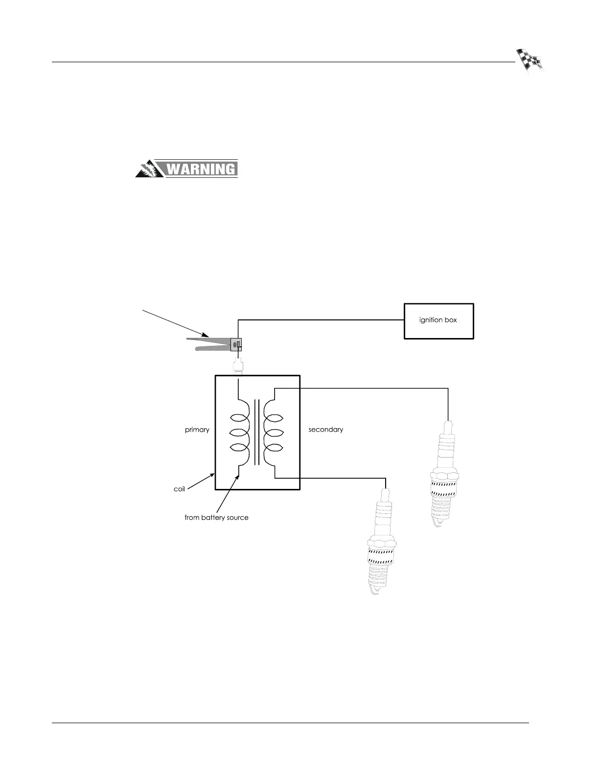
1 Clip the primary inductive pickup to the primary wire of the coil opposite the
battery source.
2 Route the primary wire cable to the dyno electronics RPM module making sure
the cable is clear of devices that produce electronic noise.
Note: You must ground the vehicle to the dyno for the electronics to function
properly.
Figure 5-3: Tachometer Pickup Primary Inductive
connect the primary
pickup opposite the
battery source