16 8-10 kVA, 50/60 Hz (1-phase input) &
8-15 kVA, 50/60 Hz (3-phase input)
P-164000341
User's Guide Revision 1
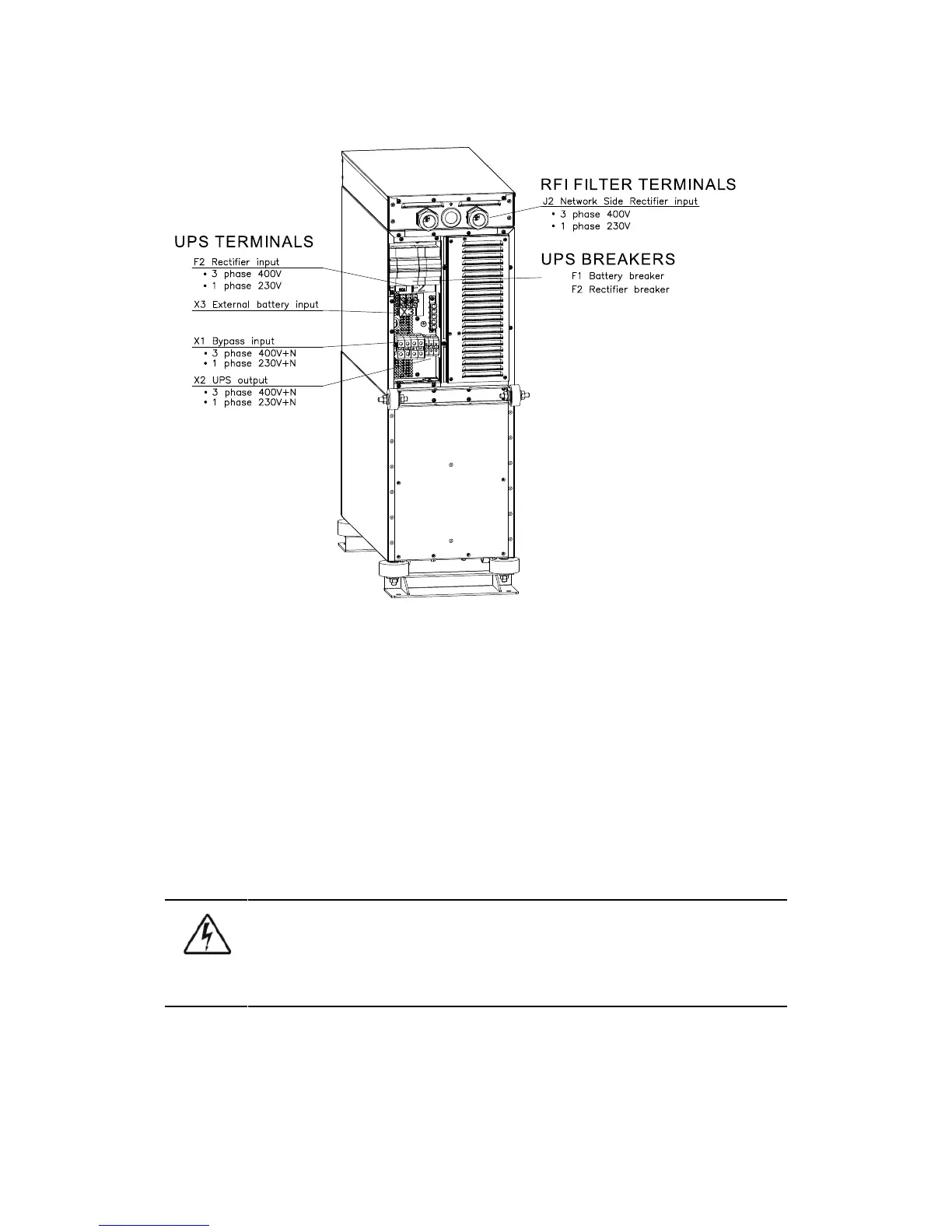
6.2.1 UPS models without an internal transformer
Figure 6-1: The location of the power terminals for UPS unit without an internal transformer
The installation procedure for models without an internal transformer is described below.
1. Remove the cover(s) of the terminal box of the power cables with a screwdriver. In TA models
rectifier input cables are connected to the filter, which is located on top of the unit. Refer to the
dimensional drawing for the correct location of the unit.
2. Slide the cables through the grommets of the connection box.
3. Connect the conductors of the rectifier and bypass input cables to the proper terminals. With
single phase unit it is recommended to use the same phases for rectifier and bypass inputs.
4. Connect the conductors of the load cable to the proper terminals.
5. Connect the conductors of an external battery cabinet cable to the external battery +, - and
PE terminals. Check for the correct polarity. See Chapter 6.3 External Battery Cabinet (EBC)
installation procedure on page 37.
WARNING
If available, the internal battery has to be disconnected first because the external battery
terminals are hazardous due to the parallel battery string.
6. Secure the cables with the grommets in the connection box.
7. Fasten the cover of the terminal box and filter enclosure with a screwdriver.