P-164000341 8-10 kVA, 50/60 Hz (1-phase input) &
8-15 kVA, 50/60 Hz (3-phase input)
75
Revision 1 User's Guide
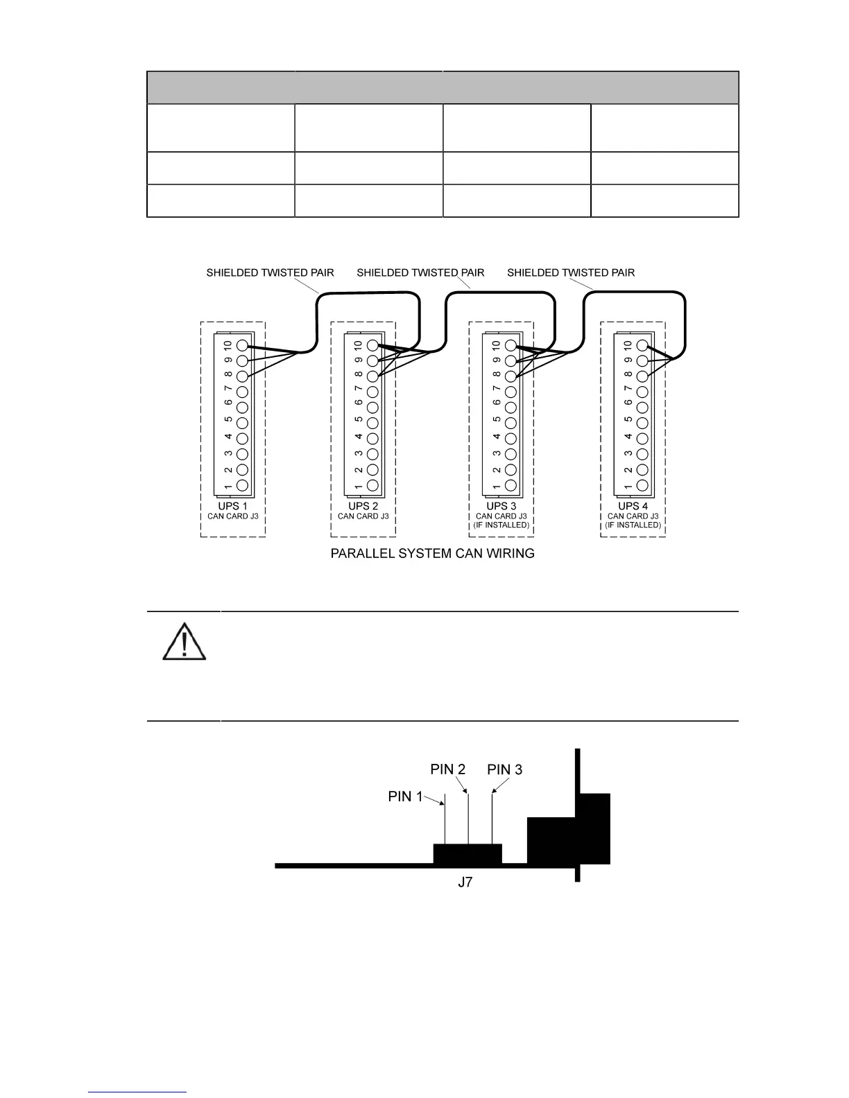
Communication Wiring Termination
From UPS 1 CAN card To UPS 2 CAN card To UPS 3 CAN card (if
installed)
To UPS 4 CAN card (if
installed)
J3-8 (L) J3-8 (L) J3-8 (L) J3-8 (L)
J3-9 (H) J3-9 (H) J3-9 (H) J3-9 (H)
Table 10-4: Communication Wiring Termination
Figure 10-10: Communication cabling wiring
NOTE
XSlot Hot Sync card has built-in termination resistor enabled by a jumper J7. The default
jumper setting without termination resistor is J7: Pin 2-3. The first and the last UPS modules
should have the termination resistor enabled by connecting Pins 1 and 2 with the jumper J7.
Default setting: Resistor ON: PIN 1 and PIN 2 connected, No resistor: PIN 2 and PIN 3 connected
Figure 10-11: XSlot HotSync card and jumper settings