74 8-10 kVA, 50/60 Hz (1-phase input) &
8-15 kVA, 50/60 Hz (3-phase input)
P-164000341
User's Guide Revision 1
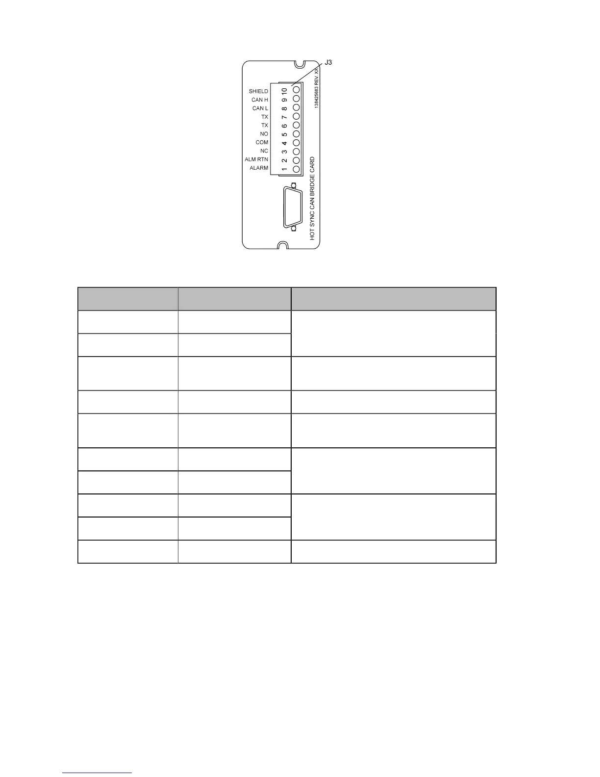
Figure 10-9: XSlot Hot Sync card and terminal interface
Terminal J3 Name Description
1 Alarm
2 Alarm Rtn
Programmable UPS alarm. Activated by a re-
mote dry contact closure.
3 Alarm Relay NC Normally-closed contact opens when UPS is on
bypass.
4 Alarm Relay Com Bypass contact return.
5 Alarm Relay NO Normally-closed contact closes when UPS is
on bypass.
6 TX
7 TX
Remote Monitor Panel (RMP). Relay Interface
Module (RIM), or Supervisory Contact Module
(SCM) Connections.
8 CAN L
9 CAN H
Controller Area Network (CAN) Input for parallel
operation.
10 Shield
Table 10-3: Description for figure XSlot Hot Sync card and terminal interface
The Hot Sync communication wiring procedure should be done with shielded twisted pair (STP) as
presented in the figure below. The maximum length of the cable is 40 m with shield connected to the
terminal pin 10 from end of the both cables. Pay attention that you don’t mix the polarity among the
UPS modules.